Variable-inductor electronic ballasts
An inductive and variable technology, used in electric light sources, electrical components, sustainable buildings, etc., can solve problems such as low-cost advantages and complex power management systems
- Summary
- Abstract
- Description
- Claims
- Application Information
AI Technical Summary
Problems solved by technology
Method used
Image
Examples
Embodiment Construction
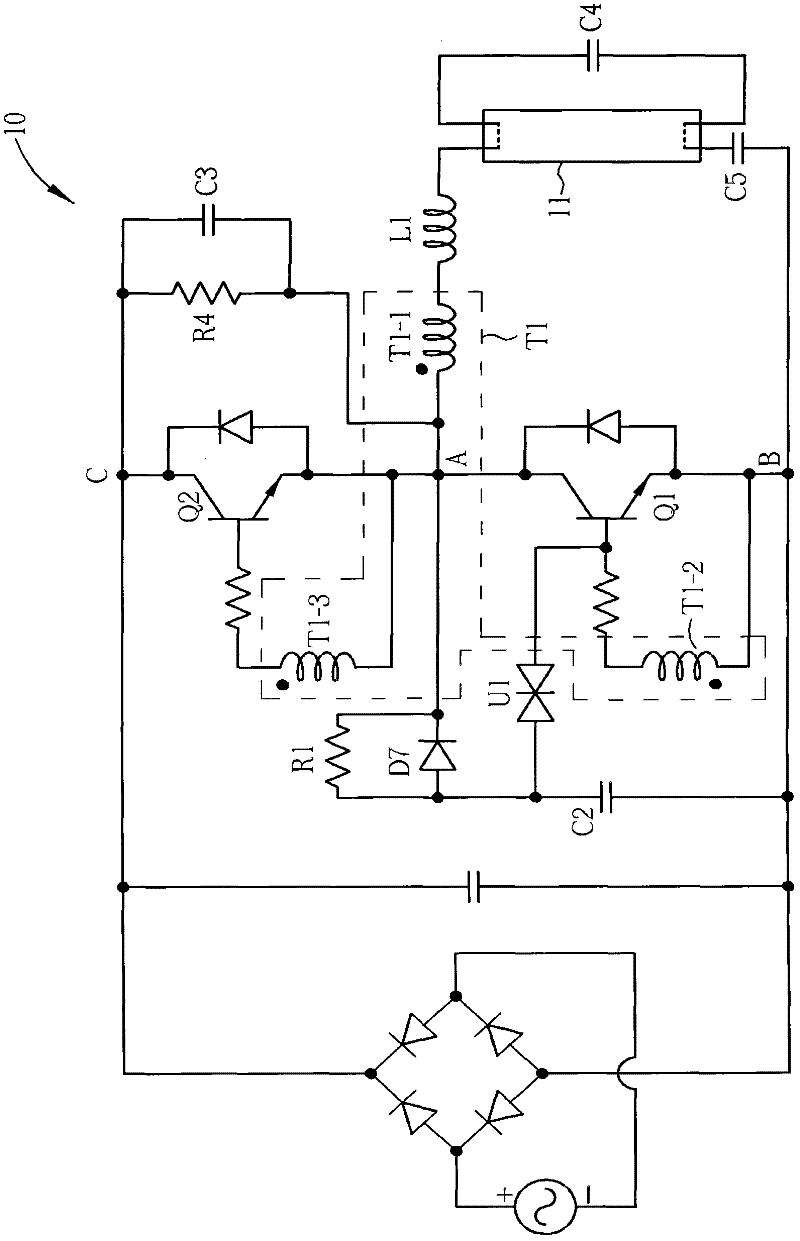
[0042] Figure 2A is description figure 1 The basic CFL has a load branch of constant inductance between nodes A and B. Capacitor C5 is a DC blocking capacitor. For the self-oscillating half-bridge converter, although the operating frequency F of the self-oscillating half-bridge converter is mainly determined by the inductor L1 and the capacitor C4, it can be further determined by the impedance of the fluorescent tube 11, the transformer T1 ( The characteristics of winding T1-1) and the reverse recovery time of transistors Q1 and Q2 are corrected. Since the square wave signal output from the node A has a fixed amplitude, the power of the fluorescent tube 11 can be determined by the impedance Z at the operating frequency F.
[0043] Please refer to Figure 2B , when the switch S1 is closed, the additional inductor L2 is connected in series with the inductor L1 to increase the ballast inductance. for illustration Figure 2B , Figure 2B The additional inductor L2 in is el...
PUM
 Abstract
Description
Claims
Application Information
 - R&D
- Intellectual Property
- Life Sciences
- Materials
- Tech Scout
- Unparalleled Data Quality
- Higher Quality Content
- 60% Fewer Hallucinations
Browse by: Latest US Patents, China's latest patents, Technical Efficacy Thesaurus, Application Domain, Technology Topic, Popular Technical Reports.
© 2025 PatSnap. All rights reserved.Legal|Privacy policy|Modern Slavery Act Transparency Statement|Sitemap|About US| Contact US: help@patsnap.com


