Magnetic trigger mechanism

A magnetic trigger and yoke technology, applied in the direction of magnets, electromagnets, magnetic objects, etc., can solve the problems of large metal friction, guiding the armature, difficult thrust seat, etc., achieve high production reliability, and prevent the armature from tilting , The effect of small electricity triggering energy

Active Publication Date: 2012-07-04
JOHNSON ELECTRIC DRESDEN
View PDF15 Cites 14 Cited by
  • Summary
  • Abstract
  • Description
  • Claims
  • Application Information

AI Technical Summary

Problems solved by technology

However, the many schemes in favor of the spring constant make it difficult to guide and / or orient the armature on the thrust seat
However, when the spring is guided in the armature, a large metallic friction is obtained

Method used


Image

  • Magnetic trigger mechanism
  • Magnetic trigger mechanism
  • Magnetic trigger mechanism

Examples


Embodiment Construction

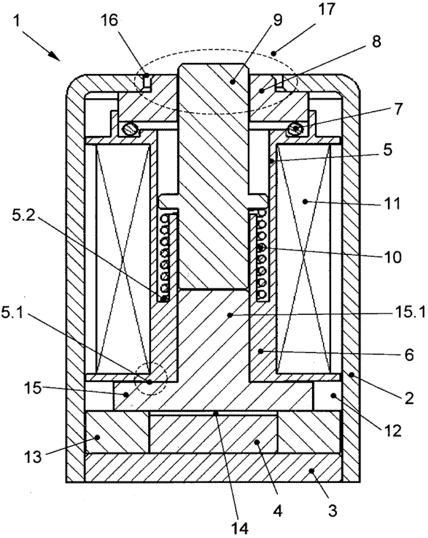
[0059] figure 1 A cross-sectional view of a magnetic trigger 1 according to the invention is shown. The yoke 2 of the magnetic trigger 1 is constituted by a housing or a frame, and has an armature opening 17 disposed on a first end face and a bottom plate disposed on a second opposite end face for closing the housing. The excitation coil 11 and the coil body 5 receiving the excitation coil 11 are arranged inside the yoke 2 . The coil body 5 has a guide part in the form of a guide sleeve, which has a coaxial groove 5.2. A spring element 10 formed as a compression spring is arranged in this groove 5.2. The armature 9 is guided in one half of this guide sleeve. The journal 15.1 of the thrust seat 15, which is made of extremely permeable material, is pressed into the other half of the guide sleeve. The second end of the armature 9 facing the armature opening 17 is additionally guided via the central ring 8 arranged in the armature opening 17 . The tolerance chain is thus kept...


PUM


Abstract

The invention relates to a magnetic trigger mechanism at least comprising a yoke having an armature opening, in which yoke an armature is placed, which armature is coaxially surrounded by at least one section of the coil body having at least one excitation coil and which is acted on by the force of a preloaded spring element and which remains in a first end position due to the magnetic retaining force of a permanent magnet when current is not flowing through the excitation coil, the permanent magnet being arranged in the area of the first end of the armature together with a base extending between the armature and the permanent magnet, and the second end position of the armature being achieved by means of a brief flow of current through the excitation coil together with the accompanying lowering of the magnetic retaining force and the spring force, which is effective then. The invention is characterized in that the first end of the armature, which first end faces away from the armature opening, is guided in the coil body in a centered manner, and the second of the armature, which second end faces the armature opening, is likewise guided in a centered manner by means of a centering ring centered in the coil body, the highly permeable centering ring lies against the yoke at the armature opening and can move radially relative to the yoke, the base is centered in the coil body, the centering ring together with the coil body ensuring that the armature lies flat in the area of the first end without tipping and always guaranteeing maximum retaining forces due to the armature lying flat, the spring element having a larger diameter than the armature, and the magnetic flux commutating upon triggering from a series connection to a parallel connection.

Description

technical field [0001] The invention relates to a magnetic trigger having at least a magnetic yoke with an armature opening, the armature being arranged inside the yoke, wherein the armature is coaxially surrounded by at least part of a coil body with at least one excitation coil and is preloaded by a spring Force biasing of the element, wherein when current does not flow through the excitation coil, the armature remains in the first end position due to the magnetic holding force of the permanent magnet, wherein the permanent magnet and the armature extending between the armature and the permanent magnet A thrust seat (socket) is arranged together in the region of the first end of the armature, and this is achieved by passing a current briefly through the excitation coil simultaneously with the reduction of the magnetic holding force and the simultaneous reduction of the effective spring force. The second end position of the armature. Background technique [0002] Many vari...

Claims


Application Information

Patent Timeline
Patent Type & Authority Applications(China)
IPC IPC(8): H01F7/16H01H71/32
CPCH01F7/13H01F2007/1669H01H71/322H01F7/1615
Inventor M·库尔克T·罗斯切克
Owner JOHNSON ELECTRIC DRESDEN
Why Eureka
Try Eureka