Self-running shoes

A self-running and driving arm technology, applied in the field of self-running shoes, can solve the problems of small application range and labor-intensive use, and achieve the effects of wide application range, improved safety, and simple use method

Inactive Publication Date: 2014-06-25
王葆敏
View PDF7 Cites 0 Cited by
  • Summary
  • Abstract
  • Description
  • Claims
  • Application Information

AI Technical Summary

Problems solved by technology

[0003] The purpose of the present invention is to provide a self-running shoe to solve the problems existing in the existing roller skates that special skills are required, laborious to use, and limited scope of application

Method used


Image

  • Self-running shoes
  • Self-running shoes
  • Self-running shoes

Examples


Embodiment Construction

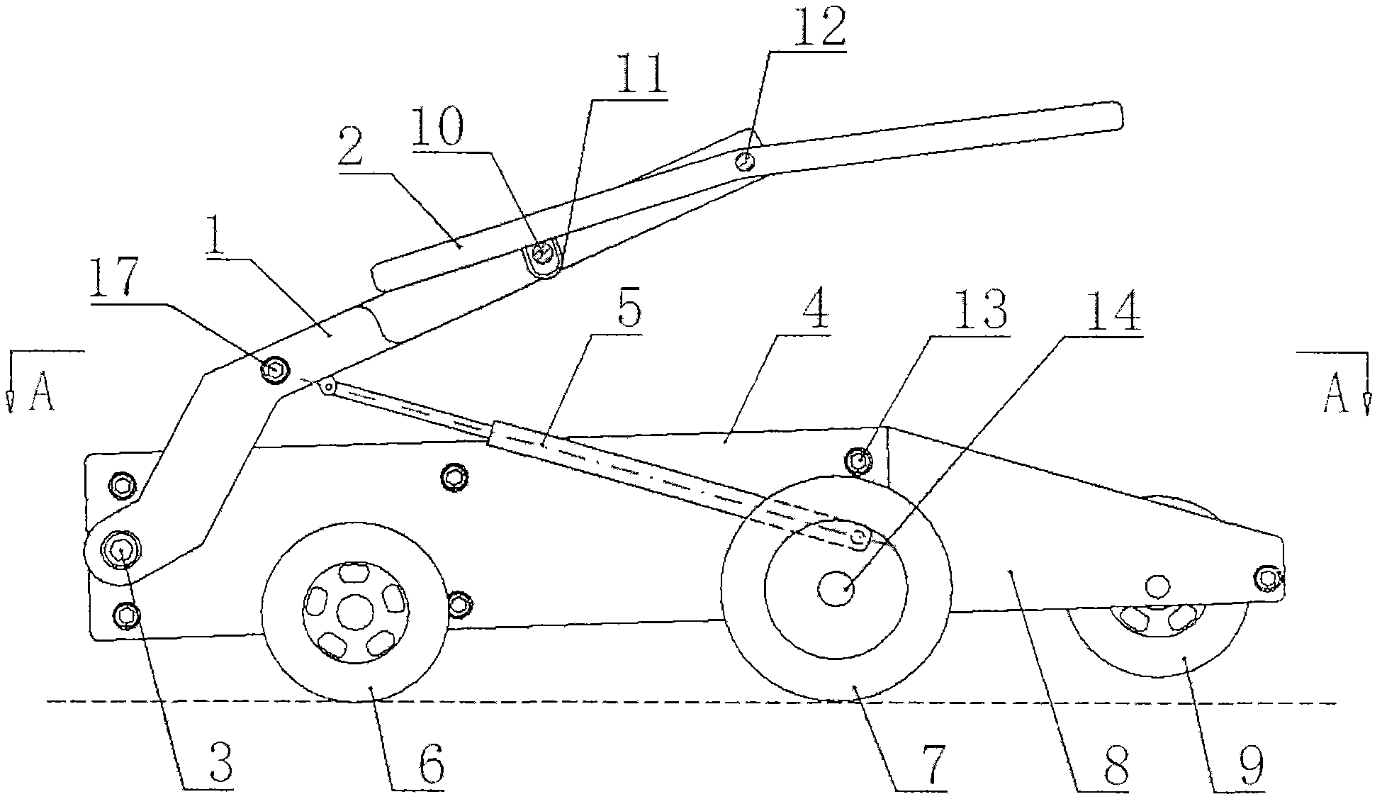
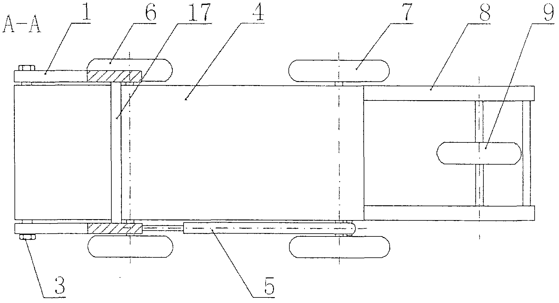
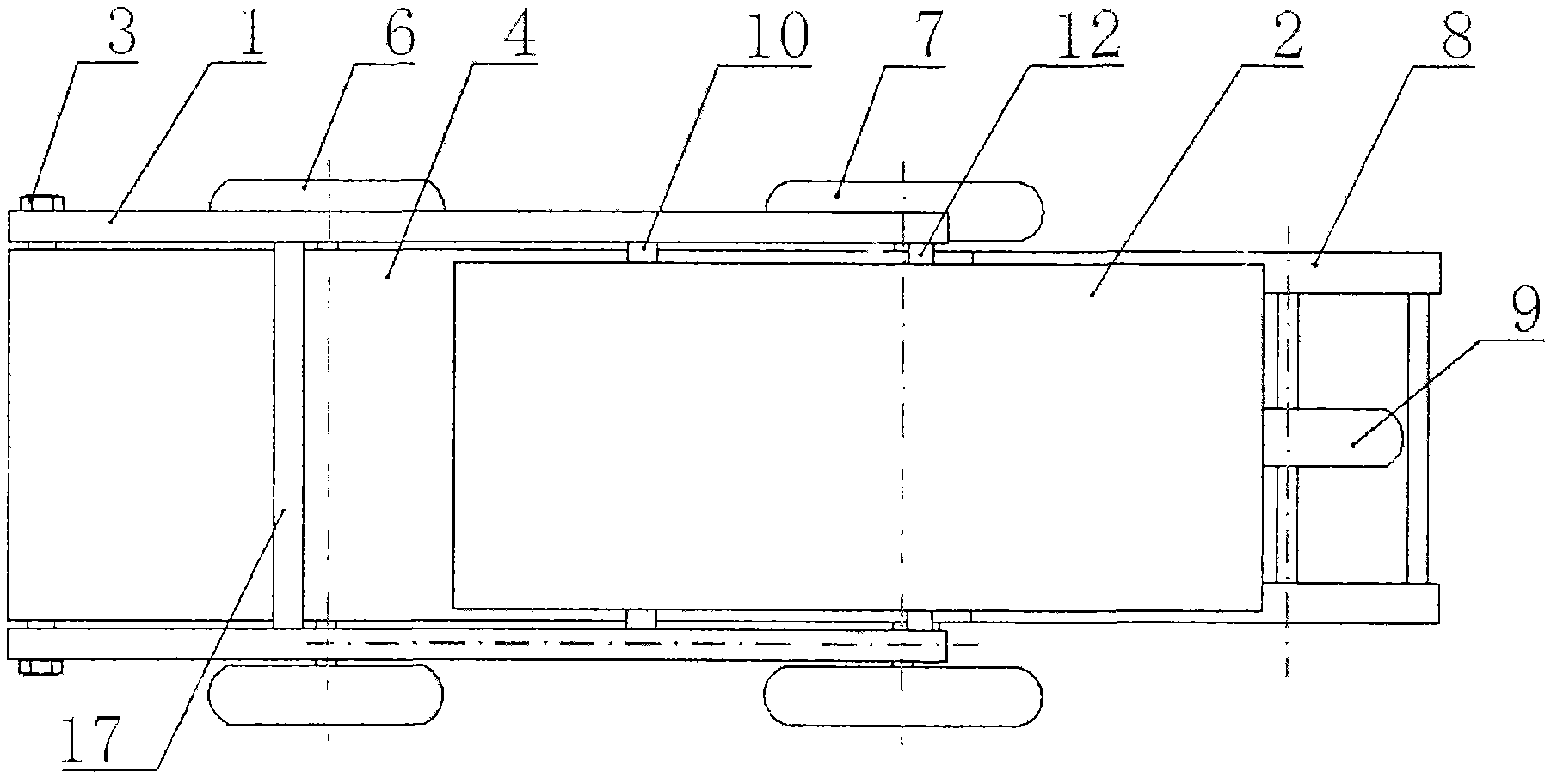
[0019] see Figure 1 to Figure 5 , this embodiment of a self-running shoe of the present invention is characterized in that a main shaft 3 is installed at the front end of the speed-increasing box 4, and the two ends of the main shaft 3 are respectively connected with the front end of a driving arm 1. Between the arms 1, a limit rod 17, a drive arm connecting rod 10 and a pedal hinged shaft 12 (equivalent to three driving arm connecting rods) are respectively provided from front to back. Between the rear ends of the drive arms 1, the middle part of the pedal hinged shaft 12 is hinged with the pedal 2. A pair of front wheels 6 and a pair of driving wheels 7 are respectively installed on both sides below the front and the rear of the speed increasing case 4, and a sector gear 41 (for driving gear), a driven gear 44 is installed on the driving wheel shaft 14 equipped with the driving wheel 7, and an intermediate gear set 43 is housed between the sector gear 41 and the driven gea...


PUM


Abstract

The invention provides a pair of self-running shoes. The self-running shoes are characterized in that the front end of a speed increasing box is provided with a main shaft; two ends of the main shaft are respectively connected with the front end of one actuating arm; at least two actuating arm connecting rods are connected between the two actuating arms; and the back ends of the actuating arms are hinged with the middle of pedal plates by pedal plate hinging shafts; two sides below the front part and the back part of the speed increasing box are respectively provided with a pair of front wheels and a pair of driving wheels; driving gears and driven gears are respectively arranged on the main shafts in the speed increasing box and driving wheel shafts provided with the driving wheels; and middle gear groups are arranged between the driving gears and the driven gears; overrun clutches are arranged on the driving gears and any gears of the middle gear groups or the driven gears; and resetting springing devices are arranged between the actuating arms and the speed increasing box. The self-running shoes have the advantages that the gravity which is alternately applied by two feet is taken as a forward power, so that the quick forwarding is realized. Thus, the self-running shoes are very labor-saving, convenient to use, suitable for the use of most people, and wide in applicable scope.

Description

technical field [0001] The invention relates to a self-running shoe, which is a fast walking-replacing device designed according to the fact that the wheels under the feet are rotated by the gravity of the person, and the two feet are alternately lifted and lowered when the person walks. Background technique [0002] At present, the best and practical device to use one's own power instead of walking is a bicycle, and roller skates can only be used as toys. The bicycle is driven by the circular motion of the two feet to drive the wheel connected to the flywheel to rotate. In order to make the circular motion of the two feet, the buttocks must be erected. The roller skates rely on one foot to step backwards on the ground to generate forward power, which not only requires special skills, but also requires a lot of effort to use, so it is not suitable for ordinary people to use. Contents of the invention [0003] The present invention aims to provide a self-running shoe to so...

Claims


Application Information

Patent Timeline
Patent Type & Authority Patents(China)
IPC IPC(8): A63C17/12A63C17/26A63C17/14A63C17/04
Inventor 王葆敏
Owner 王葆敏
Why Eureka
Try Eureka