
Method for punching high bosses on metal sheets and punch utilized in method

A sheet metal and punch technology, applied in the field of stamping high bosses on sheet metal, methods and punches, can solve the problems of material tearing, boss falling off, component failure, etc., to enhance the axial pulling force and lateral force Bearing capacity, preventing tear bosses from falling off, increasing straight body height and strength

Inactive Publication Date: 2015-06-10
深圳亿和模具制造有限公司
View PDF6 Cites 0 Cited by
  • Summary
  • Abstract
  • Description
  • Claims
  • Application Information

AI Technical Summary

Problems solved by technology

like figure 1 As shown, the current method of processing the boss on the sheet metal is to press the chamfer on the top of the punch into the sheet metal base material, so that the material in the base material overflows to the concave cavity and forms a deep-drawn hollow protrusion on the opposite side of the base metal. Since the thickness of the base material determines the height of the boss, the height and thickness of the boss formed by the existing process method are limited.
Especially when the thickness of the sheet metal is less than 1.2mm, it is very difficult to process the effective straight body height of more than 50% of the material thickness on the sheet metal because there is not enough material to be squeezed into the head of the boss
Moreover, when the high boss is stamped and processed by the existing technology, when the height of the boss reaches the limit of the material thickness, it will easily cause the material to tear, causing the boss to fall off, and it cannot be used for positioning during use, which will cause the entire part to fail.

Method used


Image

  • Method for punching high bosses on metal sheets and punch utilized in method
  • Method for punching high bosses on metal sheets and punch utilized in method
  • Method for punching high bosses on metal sheets and punch utilized in method

Examples


Embodiment Construction

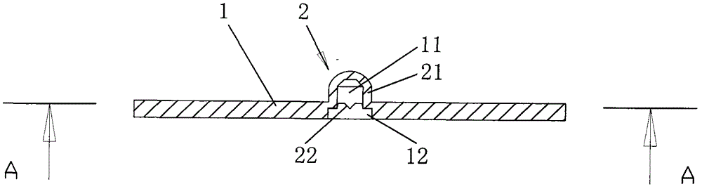
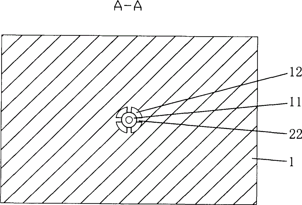
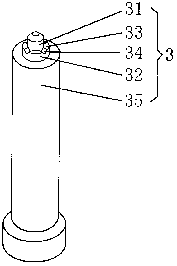
[0023] The method for stamping high bosses on sheet metal in the present invention can be realized by processing a special punch 3 and cooperating with a conventional stamping die. type settings. Such as figure 1 , figure 2 and image 3 As shown, the forming area 11 of the sheet metal base material 1 is extruded, so that the material in the forming area 11 rises under the action of the punch 3 to form a raised area 21; The rising area 21 rises, and its wall thickness gradually becomes thinner during the deep drawing process; at the later stage of the aforementioned deep drawing, the metal material in the material supplement area 12 located around the forming area 11 of the sheet metal base material 1 is simultaneously extruded toward the uplift direction Accumulation, the accumulated metal material flows to the raised area 21 to fill the thinned part of the raised area 21 due to being drawn, so that the raised area 21 can be continuously added during the continuous drawing...


PUM


Abstract

The invention discloses a method for punching high bosses on metal sheets, which includes steps of forming bosses, drawing bosses, stacking and filling, and shaping and setting, and particularly includes squeezing a forming region of a base metal sheet to form a projection region, drawing the projection region to the projection direction, squeezing and stacking metal materials in a material refilling region around the forming region of the base metal sheet to the projection direction simultaneously at the post stage of drawing, enabling the stacked metal materials to flow to the projection region, and then continuously drawing the projection region to reach the set height until forming the required high boss. The punch utilized in the method is provided with a working region having a stepped structure, and material filling is realized by squeezing the end face formed by the stepped structure. The materials around the boss forming region are squeezed by external force to flow to the projection region plastically, namely the materials are filled to the main part of the forming boss, so that the common straight height and strength of the bosses are increased and high bosses can also be punched on thinner base metal sheets and prevented from falling off.

Description

【Technical field】 [0001] The invention relates to a stamping and forming technology of a boss, in particular to a method and a punch for stamping a high boss on a sheet metal. 【Background technique】 [0002] In the stamping industry, bosses are often processed on sheet metal products. These bosses are mainly used for assembly positioning or to withstand lateral forces. Forming bosses on precision sheet metals are widely used. Such as figure 1 As shown, the current method of processing the boss on the sheet metal is to press the chamfer at the top of the punch into the sheet metal base material, so that the material in the base material overflows to the concave cavity and forms a deep-drawn hollow protrusion on the opposite side of the base metal. Since the thickness of the base material determines the height of the boss, the height and thickness of the boss formed by the existing process method are limited. Especially when the thickness of the sheet metal is lower than 1.2...

Claims


Application Information

Patent Timeline
Patent Type & Authority Patents(China)
IPC IPC(8): B21D13/02B21D37/00
Inventor 张文兵
Owner 深圳亿和模具制造有限公司
Features
  • Generate Ideas
  • Intellectual Property
  • Life Sciences
  • Materials
  • Tech Scout
  • Unparalleled Data Quality
  • Higher Quality Content
  • 60% Fewer Hallucinations
Learn More