Eureka AIR delivers breakthrough ideas for toughest innovation challenges, trusted by R&D personnel around the world.

Squeeze riveter with combined jig

A combination fixture and riveting machine technology, applied in the mechanical field, can solve the problems of workpiece damage, difficulty in replacement, and difficult position correction, etc., and achieve the effect of convenient disassembly

Inactive Publication Date: 2012-07-11
SIP GOLDWAY TECH
View PDF10 Cites 7 Cited by
  • Summary
  • Abstract
  • Description
  • Claims
  • Application Information

AI Technical Summary

Problems solved by technology

[0002] At present, riveting, as a commonly used fixed connection method, has a wide range of applications. The existing workpieces for riveting machines are generally used to fix the fixtures to be riveted. The jigs are fixed and difficult to replace. The jig is not easy to correct the position, and it is easy to cause damage to the workpiece
There is not yet a riveting machine with a fixture that can be easily replaced and fixed firmly

Method used


Image

  • Squeeze riveter with combined jig
  • Squeeze riveter with combined jig
  • Squeeze riveter with combined jig

Examples


Embodiment Construction

[0013] The present invention will be specifically introduced below in conjunction with the accompanying drawings and specific embodiments.

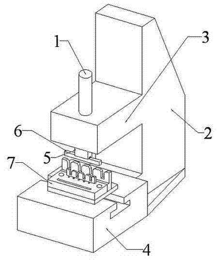
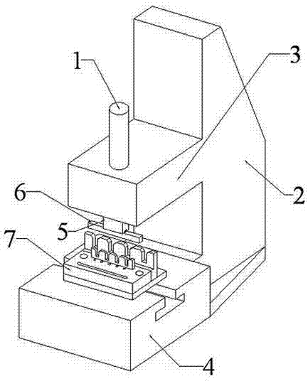
[0014] refer to figure 1 with figure 2 , The riveting machine with combined jig of the present invention includes: air cylinder 1, body 2, pressure head 5, upper die 6 for riveting, lower die assembly 7 for riveting.

[0015] Wherein, the upper half of the body 1 forms a suspension part 2 protruding forward, the lower half of the body 1 forms a fixed seat 3 protruding forward, the cylinder barrel of the cylinder 1 is fixedly connected with the suspension part, and the piston rod of the cylinder 1 The end is fixedly connected with a pressure head 5, the pressure head 5 is fixedly connected with a riveting upper die 6, and the riveting lower die assembly 7 is fixed above the fixing seat 3.

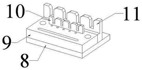
[0016] Such as figure 2 As shown, as a preferred solution, the lower press die assembly 7 includes: a base plate 8, a lower template 9, a first p...


PUM


Abstract

The invention discloses a squeeze riveter with a combined jig, comprising an air cylinder. The squeeze riveter with the combined jig is characterized by further comprising a machine body, a rivet squeezing upper die and a rivet squeezing lower die subassembly, wherein a suspension part which protrudes forwards is formed at the upper half part of the machine body and a fixing seat which protrudes forwards is formed at the lower half part of the machine body; a cylinder of the air cylinder is fixedly connected with the suspension part and the end part of a piston rod of the air cylinder is fixedly connected with a squeeze head; the squeeze head is fixedly connected with the rivet squeezing upper die and the rivet squeezing lower die subassembly is fixedly arranged above the fixing seat. The squeeze riveter with the combined jig disclosed by the invention has the beneficial effects that: the rivet squeezing upper die and the rivet squeezing lower die subassembly are conveniently detached and the squeeze riveter is applicable to a plurality of conditions; and the rivet squeezing lower die subassembly adopts a way of combining a plurality of subassemblies so that a work piece to be machined can be effectively fixed.

Description

technical field [0001] The invention relates to a riveting machine, in particular to a riveting machine with a fixing device, and belongs to the field of machinery. Background technique [0002] At present, riveting, as a commonly used fixed connection method, has a wide range of applications. The existing workpieces for riveting machines are generally used to fix the fixtures to be riveted. The jigs are fixed and difficult to replace. It is not easy to correct the position of the special fixture, and it is easy to cause damage to the workpiece. Still do not have a kind of riveting machine that can conveniently replace and fix firm fixture now. Contents of the invention [0003] In order to solve the deficiencies of the prior art, the purpose of the present invention is to provide a riveting machine with combined jigs capable of effectively fixing the riveted parts. [0004] In order to achieve the above object, the present invention adopts the following technical solut...

Claims


Application Information

Patent Timeline
IPC IPC(8): B21D39/00
Inventor 沈皓然
Owner SIP GOLDWAY TECH
Why Eureka
Eureka Blog
Learn More