Mold for conveniently de-molding injection molded products

A technology for injection molding products and molds, which is applied in the field of molds that facilitate the demolding of injection molding products, can solve problems such as increasing production costs, and the products cannot be produced smoothly, and achieves the effect of a simple device structure.

Inactive Publication Date: 2012-07-11
SHANGHAI FUJITECH PLASTIC
View PDF0 Cites 6 Cited by
  • Summary
  • Abstract
  • Description
  • Claims
  • Application Information

AI Technical Summary

Problems solved by technology

Injection molds generally use thimbles to eject the product in the mold, but often in some special cases, injection molding has to use manual or expensive mechan...

Method used


Image

  • Mold for conveniently de-molding injection molded products
  • Mold for conveniently de-molding injection molded products

Examples


Embodiment 1

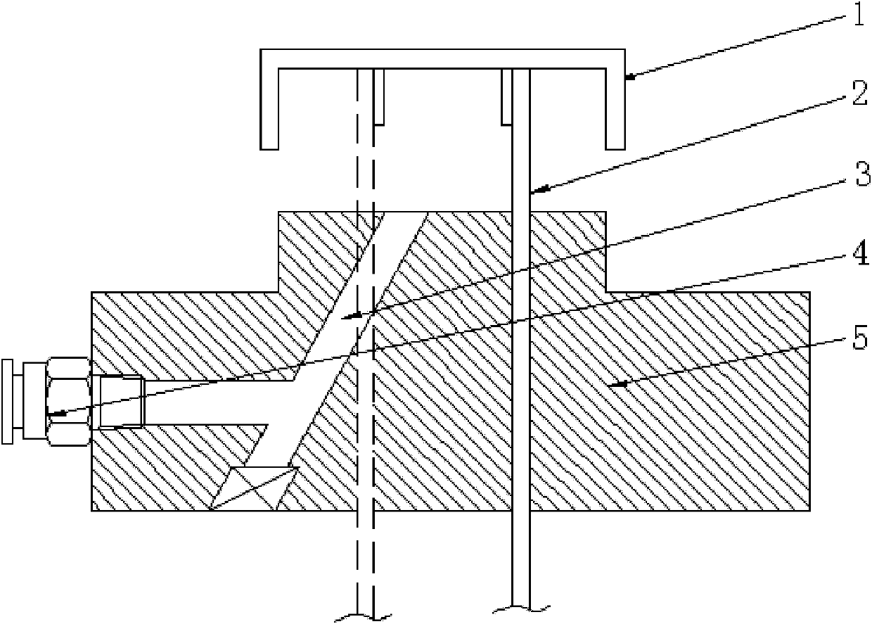
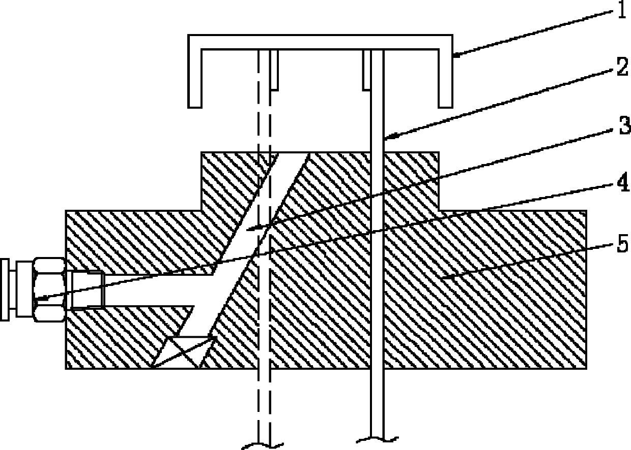
[0015] Such as figure 1 Shown, a kind of mold that is convenient for demoulding of injection molded product, this mold comprises mold body 5, blowing device. Two air hole passages 3 are arranged on the mold body 5, and one end of the air hole passage 3 is an air blowing outlet, and the air blowing outlet is arranged on the mold facing the demoulding direction of the product 1. The other ends of the pore passages 3 converge to form an air inlet, which is threadedly connected with the trachea joint 4 . The cross section of the air hole channel 3 is circular. After the product 1 is ejected from the mold for a certain distance, the blowing device sends air from the air pipe joint 4, the gas flows in along the air hole channel, and finally blows to the product 1 from the blowing outlet, so that the product 1 falls from the mold 5.

Embodiment 2

[0017] refer to figure 1 , a mold for easy demolding of injection molded products, the mold includes a mold body and an air blowing device. The mold body is provided with 30 air hole channels, and one end of the air hole channel is a blowing outlet, and the blowing outlet is arranged on the mold facing the demoulding direction of the product. The other ends of the pore channels are collected to form an air inlet, which is threadedly connected with the trachea joint. The cross-section of the stomatal channel is circular. When the product is ejected from the mold for a certain distance, the blowing device sends air from the air pipe joint, the gas flows in along the air hole channel, and finally blows to the product from the blowing outlet, so that the product falls from the mold.

Embodiment 3

[0019] refer to figure 1 , a mold for easy demolding of injection molded products, the mold includes a mold body and an air blowing device. The mold body is provided with 10 air hole channels, and one end of the air hole channel is a blowing outlet, and the blowing outlet is arranged on the mold facing the demoulding direction of the product. The other ends of the pore channels are collected to form an air inlet, which is threadedly connected with the trachea joint. The cross-section of the stomatal channel is circular. When the product is ejected from the mold for a certain distance, the blowing device sends air from the air pipe joint, the gas flows in along the air hole channel, and finally blows to the product from the blowing outlet, so that the product falls from the mold.


PUM


Abstract

The invention relates to a mold for conveniently de-molding injection molded products. The mold comprises a mold main body and a blowing device, wherein a plurality of pore channels are arranged in the mold main body; blowing outlets are arranged at one ends of the pore channels; the blowing outlets are arranged on the mold opposite to the de-molding direction of the products; the other ends of the pore channels are gathered into an air inlet; and the air inlet is in threaded connection with an air pipe connector. Compared with the prior art, the mold provided by the invention has the advantages that the products are easier to drop during a jacking process because pores for blowing are additionally arranged in the injection mold, the structure is simple, the operation is convenient and the cost is low.

Description

technical field [0001] The invention relates to an injection mold, in particular to a mold which facilitates demoulding of injection molded products. Background technique [0002] Over the years, injection molds have been pursuing to reduce the cost of injection molding, and automatic demoulding is one of the many means of reducing costs. Injection molds generally use thimbles to eject the product in the mold, but often in some special cases, injection molding has to use manual or expensive mechanical equipment to meet the problem of difficult demoulding, which not only increases production costs, It also leads to the failure of smooth production of products. Therefore, how to ensure smooth and correct demoulding of the product is a technical problem to be solved urgently. Contents of the invention [0003] The purpose of the present invention is to overcome the above-mentioned defects in the prior art and to provide an injection mold with an additional hole for air blow...

Claims


Application Information

Patent Timeline
IPC IPC(8): B29C45/26B29C45/43
Inventor 郑德明
Owner SHANGHAI FUJITECH PLASTIC
Why Eureka
Try Eureka