Pneumatic tire carcass with non-continuous ply in the bead areas

A technology for pneumatic tires and plies, which is applied to the reinforcement layers, tire parts, tire edges and other directions of pneumatic tires, can solve problems such as low performance and excessive use of tire reinforcements, reduce tire weight and cost, and prevent excessive work. , to eliminate the overlapping effect

Inactive Publication Date: 2012-07-11
THE GOODYEAR TIRE & RUBBER CO
View PDF6 Cites 1 Cited by
  • Summary
  • Abstract
  • Description
  • Claims
  • Application Information

AI Technical Summary

Problems solved by technology

Overlapping of non-continuous plies in this area can cause the tire reinforcement to become overused, thus providing a product with lower performance than desired

Method used


Image

  • Pneumatic tire carcass with non-continuous ply in the bead areas
  • Pneumatic tire carcass with non-continuous ply in the bead areas
  • Pneumatic tire carcass with non-continuous ply in the bead areas

Examples


Embodiment Construction

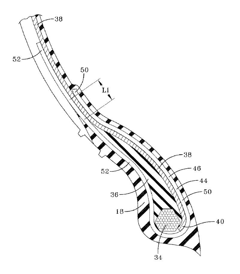
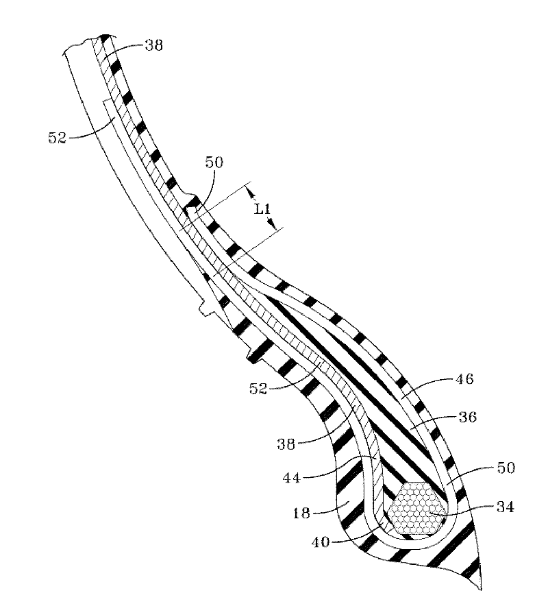
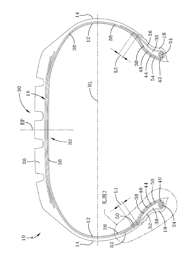
[0035] Referring now to the drawings, wherein the drawings are only for illustration of illustrated embodiments of the invention and are not intended to limit the invention, wherein like reference numerals should be understood to refer to like parts, figure 1 A pneumatic tire 10 having a carcass 30 according to one embodiment of the present invention is shown. The non-carcass portions of tire 10 may be of any conventional design and may include innerliner 12 on the inner surface of carcass 30 and sidewall rubber portions 14 , 14 on the sides of the outer surface of carcass 30 . The chafers 18 , 18 may be located below the sidewall rubber 14 on the underside of the outer surface of the carcass 30 . The belt assembly 16 may be located on a crown portion 32 of the outer surface of the carcass 30, and the tread 20 may be located on the belt assembly 16. As these components are quite familiar to those skilled in the art, further details are not provided herein. The pneumatic tire...


PUM


Abstract

A pneumatic tire comprising a carcass comprising first and second annular beads is disclosed. The carcass may comprise a continuous ply and a non-continuous ply with a first portion and a second portion. The first portion and the second portion may be located within the annular bead region. Each end of the continuous ply may be positioned between the first and second ends of the end of the non-continuous ply respectively.

Description

technical field [0001] The present invention relates generally to methods and apparatus relating to pneumatic tires, and more particularly to methods and apparatus relating to pneumatic tire carcass ply placement. Background technique [0002] It is known today to manufacture pneumatic radial tire carcasses with split or discontinuous plies. Pneumatic radial tires are typically built on tire building drums that are approximately half the final diameter of the tire. The tire diameter is then greatly increased by gas pressure as it is shaped into a belt assembly. This pressure causes the ply overlap to become stressed. To overcome this stress, tire designers are forced to "overengineer" the overlap between discontinuous plies to account for the forming stresses. This extra amount of overlap results in excessive tire weight and cost added to the final product, and provides little, if any, benefit in the final product. [0003] It is also known that the sidewall and upper cr...

Claims


Application Information

Patent Timeline
Patent Type & Authority Applications(China)
IPC IPC(8): B60C15/00B60C9/02
CPCB60C15/0018B60C15/0635
Inventor A.T.安多尼安R.D.比利亚努埃瓦R.A.诺伊鲍尔
Owner THE GOODYEAR TIRE & RUBBER CO
Why Eureka
Try Eureka