Fuel injection control device

a control device and fuel injection technology, applied in the direction of electrical control, process and machine control, instruments, etc., can solve the problems of restricted range of fuel pumping period and error between fuel injection quantity

Active Publication Date: 2010-04-15
DENSO CORP
View PDF11 Cites 13 Cited by
  • Summary
  • Abstract
  • Description
  • Claims
  • Application Information

AI Technical Summary

Benefits of technology

[0007]It is an object of the present invention to provide a fuel injection control device that inhibits an error in fuel injection quantity.
[0016]According to a fifth example aspect of the present invention, the fuel injection control device further has a range determining section for determining whether the sum of durations of ranges on an advance side and a delay side of the fuel inflow period in a combustion stabilization range is “equal to or longer than” a duration of the fuel injection period set by the injection period setting section. The combustion stabilization range is a range where a fuel injection period, in which combustion of the internal combustion engine stabilizes, can be set. The injection period changing section divides the fuel injection period set by the injection period setting section into both of the advance side range and the delay side range when a result of the determination by the range determining section is affirmative. Thus, the overlap between the fuel injection period and the fuel inflow period can be eliminated. Specifically, according to the above fifth example aspect of the present invention, even when both of the durations of the ranges on the advance side and the delay side of the fuel inflow period in the combustion stabilization range are shorter than the duration of the already-set fuel injection period, the overlap between the fuel injection period and the fuel inflow period can be eliminated by dividing the already-set fuel injection period.

Problems solved by technology

Accordingly, there is a possibility that an error arises between fuel injection quantity actually injected in the fuel injection period, which is set based on the pressure of the fuel in the accumulator before the fuel injection start, and the set fuel injection quantity.
However, since the pump section driven by the internal combustion engine repeats the suction and the discharge of the fuel in synchronization with a crank angle of the internal combustion engine, a setting range of a fuel pumping period of the pump section is restricted.

Method used


Image

  • Fuel injection control device
  • Fuel injection control device
  • Fuel injection control device

Examples


Embodiment Construction

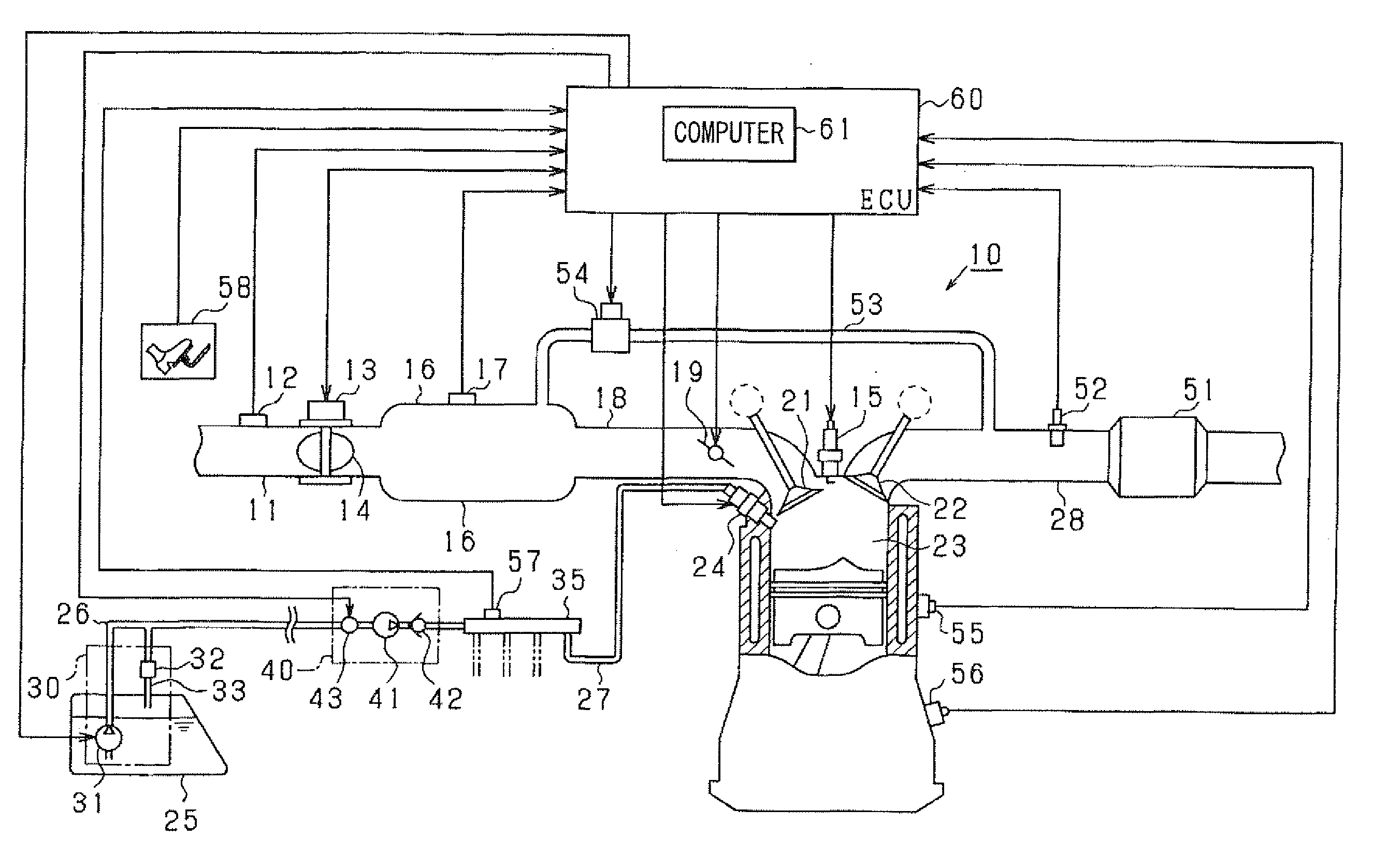
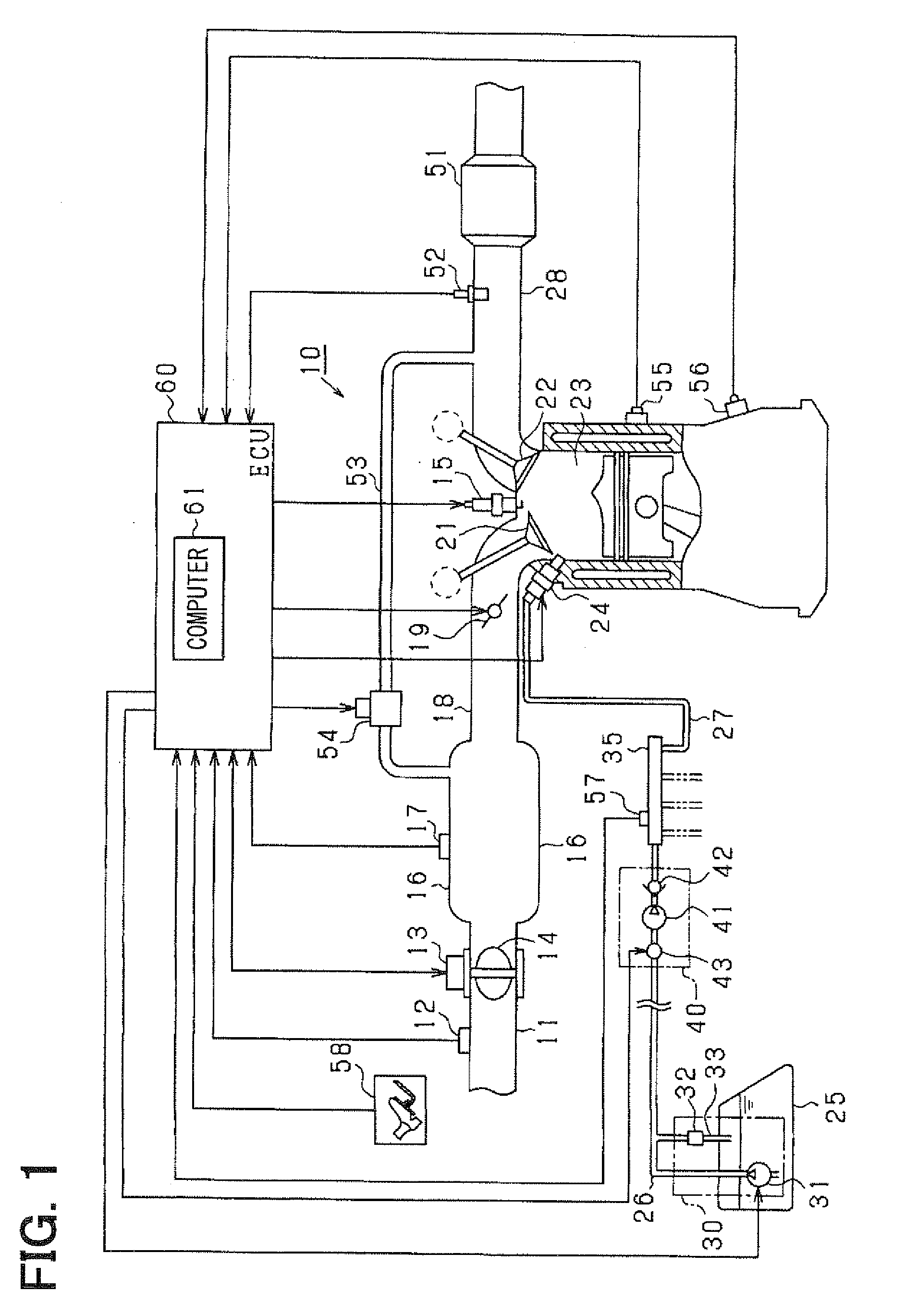
[0031]Hereafter, embodiments of the present invention will be described with reference to the drawings. The present embodiment is constructed as an engine control system for an in-vehicle multi-cylinder direct-injection gasoline engine as an internal combustion engine. The control system performs fuel injection control and the like using an electronic control unit (referred to as ECU, hereinafter) as a central device for control. FIG. 1 is a schematic construction diagram showing the entirety of the engine control system. It is assumed in the present embodiment that the engine is a four-cylinder engine.

[0032]In FIG. 1, an airflow meter 12 for sensing intake air quantity is provided in the most upstream portion of an intake pipe 11 of the engine 10. A throttle valve 14 is provided downstream of the airflow meter 12. An opening of the throttle valve 14 is regulated by a throttle actuator 13 such as a DC motor. The opening of the throttle valve 14 (throttle opening) is sensed with a th...


PUM


Abstract

A high-pressure pump section pumps fuel in a fuel tank into a delivery pipe. An injector injects the fuel in the delivery pipe directly into a combustion chamber of an engine. An ECU calculates fuel injection quantity based on an operation state of the engine and calculates fuel injection time based on the fuel injection quantity and pressure of the fuel in the delivery pipe. The ECU calculates fuel injection start timing based on the operation state of the engine. The ECU sets the fuel injection time and the fuel injection start timing as a base injection period. When a fuel inflow period, in which the high-pressure fuel flows into the delivery pipe with the fuel pumping by the high-pressure pump section, overlaps with the base injection period, the ECU changes the base injection period to eliminate or reduce the overlap.

Description

CROSS REFERENCE TO RELATED APPLICATION[0001]This application is based on and incorporates herein by reference Japanese Patent Application No. 2008-262657 filed on Oct. 9, 2008.BACKGROUND OF THE INVENTION[0002]1. Field of the Invention[0003]The present invention relates to a fuel injection control device applied to a fuel supply system that supplies fuel to an internal combustion engine.[0004]2. Description of Related Art[0005]Conventionally, as a fuel supply system of a direct-injection gasoline engine, there has been practically used a fuel supply system that has a low-pressure pump for drawing fuel from a fuel tank and for pressurizing the fuel, a high-pressure pump driven by an engine for further pressurizing the fuel discharged by the low-pressure pump and a delivery pipe for storing the fuel pumped from the high-pressure pump and that injects the high-pressure fuel in the delivery pipe from the injector directly into a cylinder of the internal combustion engine (for example, as...

Claims


Application Information

Patent Timeline
Patent Type & Authority Applications(United States)
IPC IPC(8): F02M63/00F02D41/30
CPCF02D41/3845F02D41/401F02D41/402Y02T10/44F02D2200/0604F02D2250/04F02M63/0007F02D2041/389Y02T10/40
Inventor TANAKA, MAKOTO
Owner DENSO CORP
Why Eureka
Try Eureka