Vehicle with a leaf spring element for the spring suspension of the vehicle

A technology of leaf springs and car frames, applied in the direction of vehicle springs, vehicle components, elastic suspensions, etc.

Inactive Publication Date: 2012-07-11
GM GLOBAL TECH OPERATIONS LLC
View PDF9 Cites 4 Cited by
  • Summary
  • Abstract
  • Description
  • Claims
  • Application Information

AI Technical Summary

Problems solved by technology

This leaf spring pair requires

Method used


Image

  • Vehicle with a leaf spring element for the spring suspension of the vehicle
  • Vehicle with a leaf spring element for the spring suspension of the vehicle
  • Vehicle with a leaf spring element for the spring suspension of the vehicle

Examples


Embodiment Construction

[0035] The accompanying drawings should provide a further understanding of the embodiments of the invention. These drawings illustrate embodiments in a pictorial manner and serve to explain the principles and concepts of the invention in connection with the description. Further embodiments and many of the described advantages emerge from the drawings. Elements in the figures are not necessarily shown to scale.

[0036] In the figures, identical, functionally identical and identically acting elements, features and components are provided with the same reference symbols unless otherwise specified.

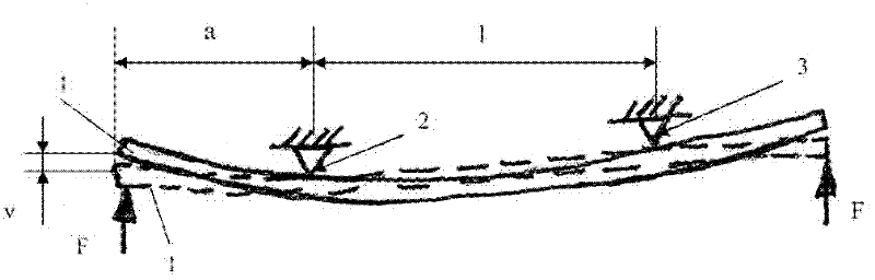
[0037] figure 1 A schematic diagram is shown of a single-layer leaf spring element 1 with a constant spring stiffness or spring stiffness c. In this case, the spring element 1 has two bearing points 2 , 3 which are spaced at a distance l from one another. The free end of the leaf spring element 1 forms here with the associated bearing point 2 a lever arm a, wherein when a force F...


PUM


Abstract

The invention relates to a vehicle, in particular a passenger car is provided with a vehicle frame having a leaf spring element for the spring suspension of the vehicle, which is mounted on the vehicle frame with two bearing points, which are designed in a manner to adjustably set a spring rate and/or a standing height of the leaf spring element. The leaf spring element is mounted on a frame of the vehicle with the two bearing points and the bearing points are designed adjustable for setting a spring rate and/or a standing height of the leaf spring element.

Description

technical field [0001] The invention relates to a motor vehicle with leaf spring elements for damping the motor vehicle. Background technique [0002] An independent suspension for vehicle wheels is described in DE 19542108A1. The independent suspension described therein has transverse leaf springs extending from wheel to wheel, the free ends of which are each articulated to the wheel carrier of the wheel via a ball joint. The transverse leaf spring is supported on the vehicle body via two eccentrically arranged symmetrical bearing points. In addition, the transverse leaf spring is supported in the vertical direction, ie in the direction of the vertical axis, by a horizontally adjustable adjusting element acting centrally on it, which is itself designed to be non-elastic. The adjustment elements described therein allow only limited horizontal adjustment. [0003] In addition, DE 3637281 A1 describes a leaf spring carrier fastened to the chassis frame. The leaf spring sup...

Claims


Application Information

Patent Timeline
IPC IPC(8): B60G17/02
CPCB60G17/00B60G17/027B60G2202/412B60G2202/42B60G2204/121B60G2204/127B60R17/02B60G2202/413B60G11/08B60G2202/114B60G11/04B60G21/053B60G2500/20B60G11/10B60G11/02B60G17/0275B60G17/02B60G17/023B60G2202/11
Inventor D.艾尔里克R.斯塔克V.赫尔德
Owner GM GLOBAL TECH OPERATIONS LLC
Why Eureka
Try Eureka