Force application element for fixing in or on fiber-plastic composite component

A technology of force components and composite components, applied in the field of force transmission components, can solve the problems of high mold costs and equipment costs, achieve good connection quality and reduce manufacturing costs

Active Publication Date: 2012-07-11
AUDI AG
View PDF6 Cites 1 Cited by
  • Summary
  • Abstract
  • Description
  • Claims
  • Application Information

AI Technical Summary

Problems solved by technology

However, the sheet molding compound (SMC) process used to manufacture such known inserts is associated with high tooling and equipment costs

Method used


Image

  • Force application element for fixing in or on fiber-plastic composite component
  • Force application element for fixing in or on fiber-plastic composite component
  • Force application element for fixing in or on fiber-plastic composite component

Examples


Embodiment Construction

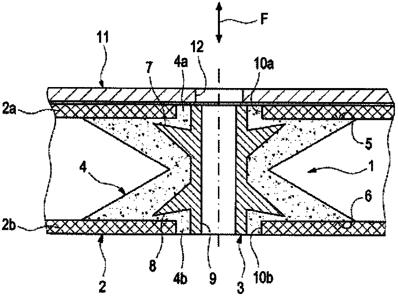
[0016] figure 1 The structural part 2 shown in includes a first FKV part 2a and a second FKV part 2b, said first and second FKV parts being made, for example, of CFK. A force transmission point is realized in this structural component 2 with the force transmission element 1 .

[0017] The force transmission element 1 is designed as a hybrid component and comprises a metal insert 3 made of steel, which is designed in the form of a sleeve in the force transmission direction F with the formation of a through-hole 9 . The metal insert 3 is enveloped in the shape of a shell by a structure 4 of BMC material, which has a substantially biconical cross-section.

[0018] A contact surface 5 for bearing against the FKV component 2 a and a contact surface 6 for abutting against the FKV component 2 b are each formed by means of the biconical end faces. Furthermore, the contact surfaces 5 and 6 transition into flanges 4a and 4b, respectively, which engage in openings 10a and 10b in the tw...


PUM


Abstract

The element (1) has a hollow cylindrical metal insert (3) which is fixed and enclosed in a plastic structure (4a,4b) having contact surface in for bearing against the fiber-plastic composite component (2,2a,2b) one plane vertically to the force application direction. The metal insert has undercuts (7, 8) which are oriented in opposite directions. The plastic structure is double-cone-shape in the plane of force transmission direction. The base surface of double cone and contact surfaces of the plastic structure are made of bulk molding compound (BMC).

Description

technical field [0001] The invention relates to a force transmission element for fastening in or on a fiber-plastic composite (FKV) component, which is designed as a hybrid component with a metal insert that holds In structures composed of synthetic materials. Furthermore, the invention relates to a FKV component as a structural part of a vehicle body, which FKV component has a force transmission point realized using the force transmission element according to the invention. Background technique [0002] Such a force transmission element designed as an insert for FKV components is known from DE 10 2008 061 463 A1, which can form at least one defined load path in the structural component. Such inserts with metal inserts are made of FKV material, ie SMC material. However, the sheet molding compound (SMC) process for producing such known inserts is associated with high tool and equipment outlay. Contents of the invention [0003] It is therefore the object of the present i...

Claims


Application Information

Patent Timeline
Patent Type & Authority Applications(China)
IPC IPC(8): F16B1/00
CPCF16B37/122B62D27/065F16B5/01B62D29/005
Inventor D・维拉姆
Owner AUDI AG
Why Eureka
Try Eureka