Eureka AIR delivers breakthrough ideas for toughest innovation challenges, trusted by R&D personnel around the world.

Oil pressure compensator

A technology of pressure compensation and oil, which is applied in the direction of fluid pressure actuation device, fluid pressure actuation system test, fluid pressure actuation system safety, etc. It can solve the problems of not reaching the compensator, equipment crushing, high cost, etc. Achieve oil shortage alarm oil compensation amount, ensure internal and external pressure balance, and light weight

Pending Publication Date: 2021-08-06
HEBEI UNIV OF TECH
View PDF0 Cites 0 Cited by
  • Summary
  • Abstract
  • Description
  • Claims
  • Application Information

AI Technical Summary

Problems solved by technology

The compensators currently used in the world are inconvenient to use and have complex structures, but they do not meet the required functions of the compensators.
For example, at present, only throttle valves, sensors, etc. can be added to the hydraulic control system, which is inefficient and expensive.
A simple deep-sea compensator currently used is to fill the oil bag with pressure-balancing oil, so that the deep-sea equipment is always in a state of internal and external pressure balance, and the equipment is not crushed. This kind of compensator is called "has Oil pressure compensator", however, this kind of conventional compensator, because the internal and external pressure is absolutely equal, when the external environment changes instantaneously, the external pressure increases instantaneously, causing the equipment to collapse

Method used


Image

  • Oil pressure compensator
  • Oil pressure compensator
  • Oil pressure compensator

Examples


Embodiment Construction

[0036] The following will clearly and completely describe the technical solutions in the embodiments of the present invention with reference to the accompanying drawings in the embodiments of the present invention. Obviously, the described embodiments are only some, not all, embodiments of the present invention. Based on the embodiments of the present invention, all other embodiments obtained by persons of ordinary skill in the art without making creative efforts belong to the protection scope of the present invention.

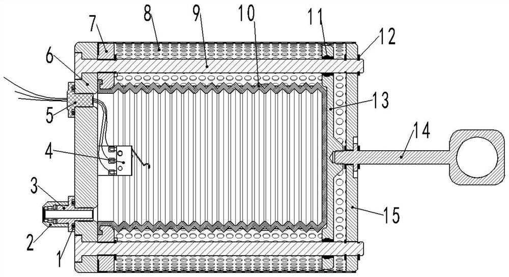
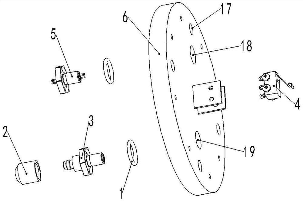
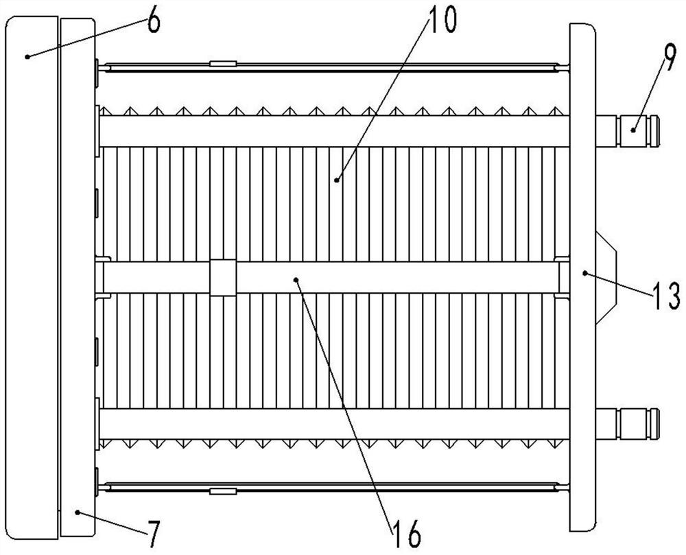
[0037] The embodiment of the present invention discloses an oil pressure compensator. This patent includes a sealing ring 1, an oil pipe fixing sleeve 2, an oil pipe plug 3, a micro switch 4, a sealing connector 5, a base 6, an oil bag gland 7, a protective Net 8, slide bar 9, stacked oil bag 10, sliding sleeve 11, opening retaining ring 12, oil bag cover 13, fixed key 14, fixed cover 15, high-strength rubber band 16.

[0038] The sealing ring 1 is placed in t...


PUM


Abstract

The invention discloses an oil pressure compensator which comprises a base. One end of an oil tube plug is detachably connected to the base, and the other end is connected with an oil tube fixing sleeve; one end of a sealing connector is detachably connected to the base; a microswitch is fixedly arranged on the base and is electrically connected with the sealing connector; an oil bag gland is fixedly mounted at the inner side of the base; the outlet end of a stacked oil bag is clamped between the base and the oil bag gland; an oil bag cover is arranged on the stacked oil bag; and the two ends of a sliding rod are fixedly connected with the base and the oil bag cover respectively. A fixed key is detachably connected to the oil bag cover; and multiple high-strength rubber bands are arranged, and the two ends of each high-strength rubber band are fixedly connected with the oil bag gland and the oil bag cover respectively. When the oil pressure compensator disclosed by the invention works, the stacked oil bag extrudes oil and then performs oil real-time compensation on equipment through an oil tube; and when the oil pressure compensator does not work, the lower end of the fixed key is in threaded connection with the oil bag cover, the oil bag cover is pulled to the position where the pulling force on the stacked oil bag is eliminated through hand pulling, and oil filling operation on the compensator can be conducted.

Description

technical field [0001] The invention relates to the technical field of underwater robots, in particular to an oil pressure compensator. Background technique [0002] The underwater robot, also known as the unmanned remote control submersible, is a kind of extreme operation robot that works underwater. The underwater environment is harsh and dangerous, and people's diving depth is limited, so underwater robots have become an important tool for developing the ocean. There are two main types of unmanned remote control submersibles: remote control submersibles with cables and remote control submersibles without cables. Among them, remote control submersibles with cables are divided into three types: self-propelled in water, towed and crawling on submarine structures. . [0003] At present, underwater robot is an industry with great technical difficulty and great market potential. Our country's technology research and development in this industry is still in an extremely backw...

Claims


Application Information

Patent Timeline
IPC IPC(8): F15B19/00F15B21/00F15B20/00
CPCF15B19/005F15B20/00F15B21/00
Inventor 武建国杜通成赵晓宇殷允东武天龙武冬兵
Owner HEBEI UNIV OF TECH
Why Eureka
Eureka Blog
Learn More