Plane friction type clutch on working shaft of ceramic roller machine

A clutch and working shaft technology, applied in friction clutches, mechanically driven clutches, clutches, etc., can solve the problems of short service life, unusable brake pads, and high noise, and achieve improved clutch effect, long service life, and low noise. Effect

Inactive Publication Date: 2012-07-11
博山宝丰陶瓷机械有限公司
View PDF7 Cites 3 Cited by
  • Summary
  • Abstract
  • Description
  • Claims
  • Application Information

AI Technical Summary

Problems solved by technology

Working in this way, the service life of the brake pads is short
When it is necessary to separate the conical clutch disc from the clutch pulley, the required separation power is very large, sometimes the working shaft vibrates, which affects the service life of the working shaft, and the noise is large when separating; when the conical clutch disc and the clutch pulley are required When combining, due to the friction on one side, the friction force is small, so it cannot be used on large ceramic rolling machines, and the noise when combining is very harsh

Method used


Image

  • Plane friction type clutch on working shaft of ceramic roller machine
  • Plane friction type clutch on working shaft of ceramic roller machine

Examples


Embodiment Construction

[0020] The present invention will be further described below in conjunction with the accompanying drawings of the embodiments.

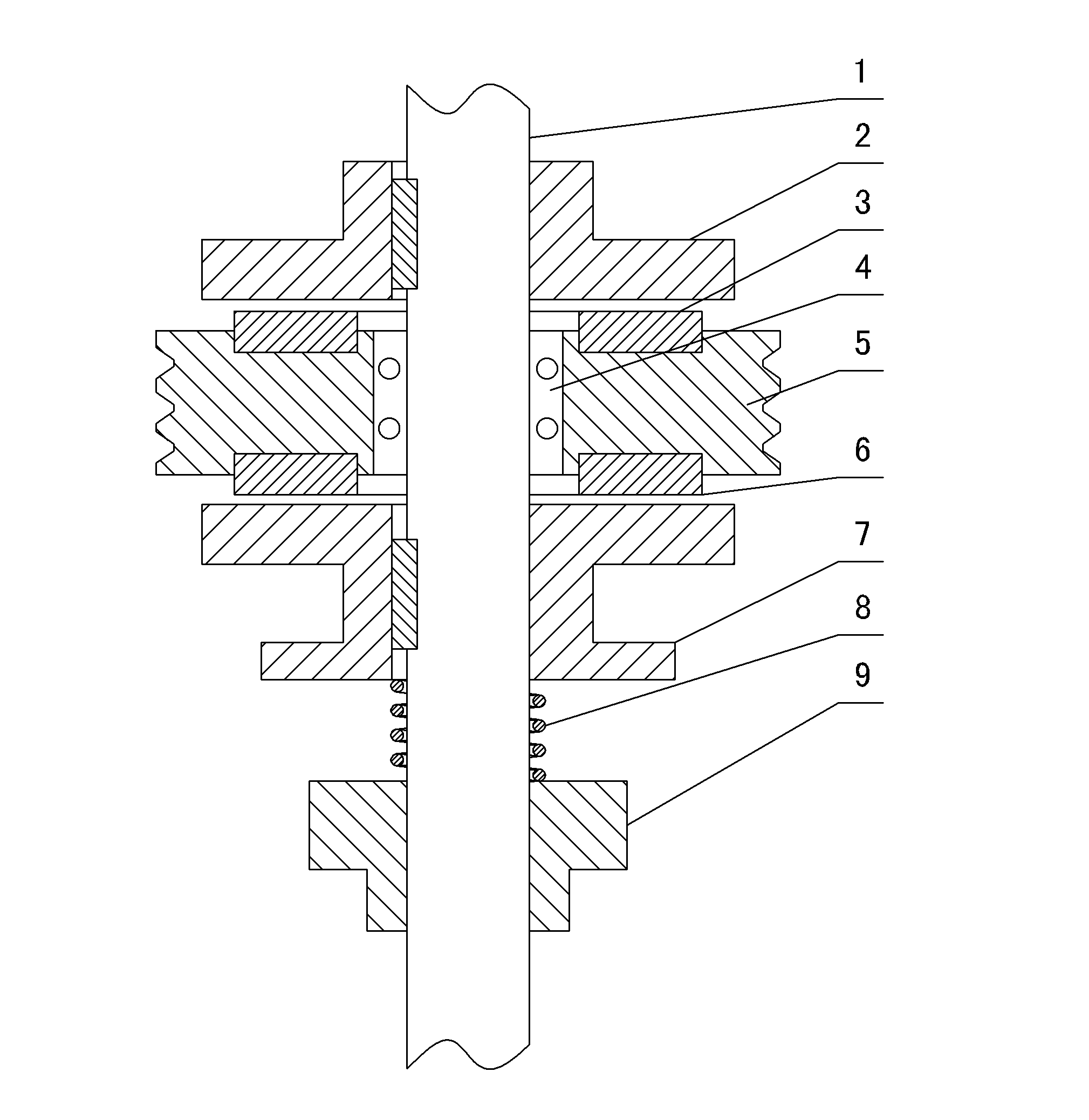
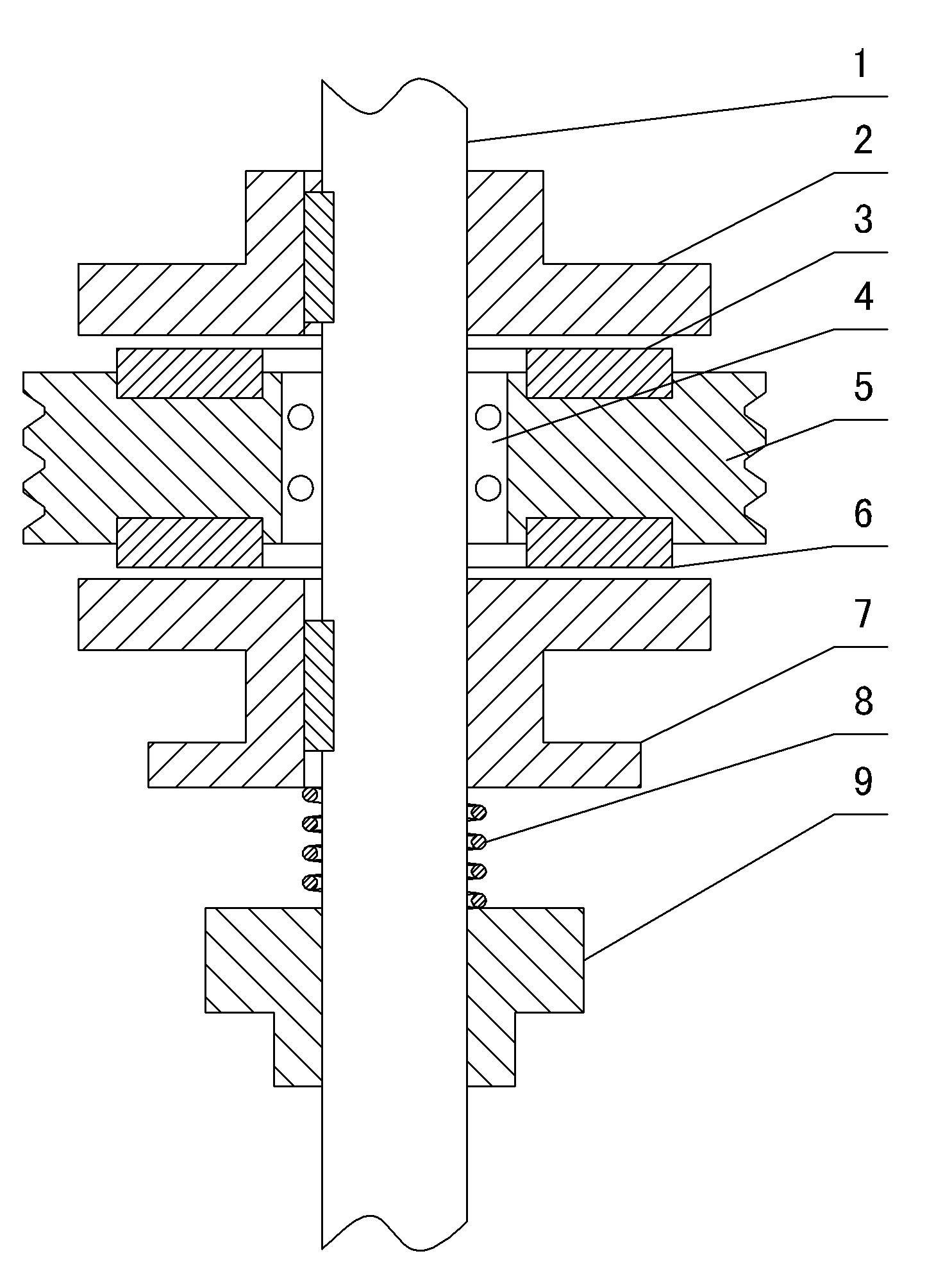
[0021] Such as figure 1 As shown, the plane friction clutch on the working shaft of the ceramic rolling machine includes the working shaft 1, the lower clutch disc 7 and the bearing 4 are installed on the working shaft 1, the outer ring of the bearing 4 is fitted with the plane clutch pulley 5, and the lower clutch disc 7 Below the planar clutch pulley 5, a lower brake shoe 6 is arranged between the planar clutch pulley 5 and the lower clutch disc 7. The end of the lower clutch disc 7 close to the lower brake shoe 6 is a plane, and the corresponding lower clutch disc 7 is provided with a pressing mechanism. The pressing mechanism includes a spring cap 9 and a spring 8. The spring cap 9 and the spring 8 are respectively set on the working shaft 1. The spring 8 is between the spring cap 9 and the lower clutch disc 7. The upper clutch disc 2 is installe...


PUM


Abstract

The invention relates to a plane friction type clutch on a working shaft of a ceramic roller machine, and belongs to the field of clutches for ceramic roller machines. The plane friction type clutch comprises the working shaft and is characterized in that: the working shaft is provided with a lower clutch plate and a bearing; a plane clutch belt wheel is sleeved on the outer ring of the bearing; the lower clutch plate is positioned below the plane clutch belt wheel; a lower brake pad is arranged between the plane clutch belt wheel and the lower clutch plate; one end of the lower clutch plate, which is close to the lower brake pad is a plane; and a compaction mechanism is opposite to the lower clutch plate. One end of the lower clutch plate, which is close to the lower brake pad is the plane, and one end of an upper clutch plate, which is closed to an upper brake pad is a plane, so during use, the plane friction type clutch has low noise and long service life; and specifically, during separation, the phenomenon that the working shaft is vibrated is avoided, and large separation power is not needed. The upper and lower surfaces of the plane clutch belt wheel have friction, so the plane friction type clutch is very practical on a large-scale ceramic roller machine.

Description

technical field [0001] The invention relates to a plane friction clutch on a working shaft of a ceramic rolling machine, which belongs to the field of ceramic rolling machine clutches. Background technique [0002] At present, the clutch used on the working shaft of the ceramic rolling machine is a conical clutch structure, which mainly includes a conical clutch disc, a clutch pulley, and a brake pad. One side of the conical clutch disc is an outer cone structure, corresponding to the conical clutch disc. The outer cone structure is provided with an inner cone structure on the clutch pulley, and a brake shoe is fixed on the inner cone structure. During use, the conical clutch disc is mounted on the working shaft through a key, and the clutch pulley is mounted on the working shaft through a bearing. When working, put the outer cone of the clutch disc into the inner cone of the clutch pulley. Under the action of the brake pads, the clutch pulley drives the clutch disc to star...

Claims


Application Information

Patent Timeline
Patent Type & Authority Applications(China)
IPC IPC(8): F16D13/38F16D13/71F16D13/68F16D13/76
Inventor 苏家宝
Owner 博山宝丰陶瓷机械有限公司
Why Eureka
Try Eureka