Handwheel clutch for use in machinery

a technology for handwheels and clutches, applied in the field of handwheel clutches for machinery, can solve the problem that the handwheel cannot drive the handwheel axle, and achieve the effects of stable clutch effect, simple structure, and convenient assembly

Inactive Publication Date: 2017-07-20
FLAIR IND ACCESSORY
View PDF3 Cites 0 Cited by
  • Summary
  • Abstract
  • Description
  • Claims
  • Application Information

AI Technical Summary

Benefits of technology

[0006]The present invention has been accomplished under the circumstances in view. It is the main object of the present invention to provide a handwheel clutch, which has the characteristics of simple structure and ease of assembling, and provides a very stable clutch effect.

Problems solved by technology

At this time, the clutch member will run idle relative to the axle sleeve, so that the handwheel cannot drive the handwheel axle to rotate.

Method used


Image

  • Handwheel clutch for use in machinery
  • Handwheel clutch for use in machinery
  • Handwheel clutch for use in machinery

Examples


Embodiment Construction

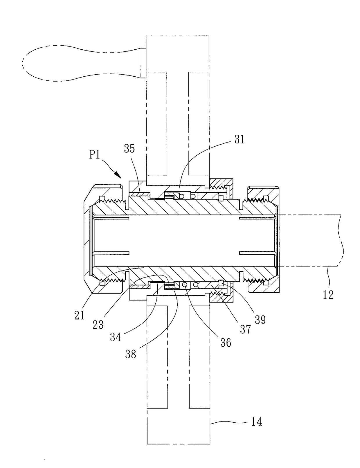
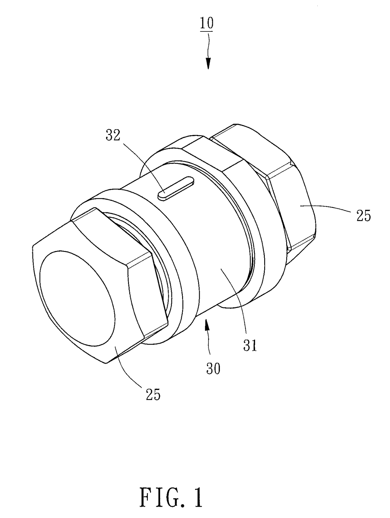
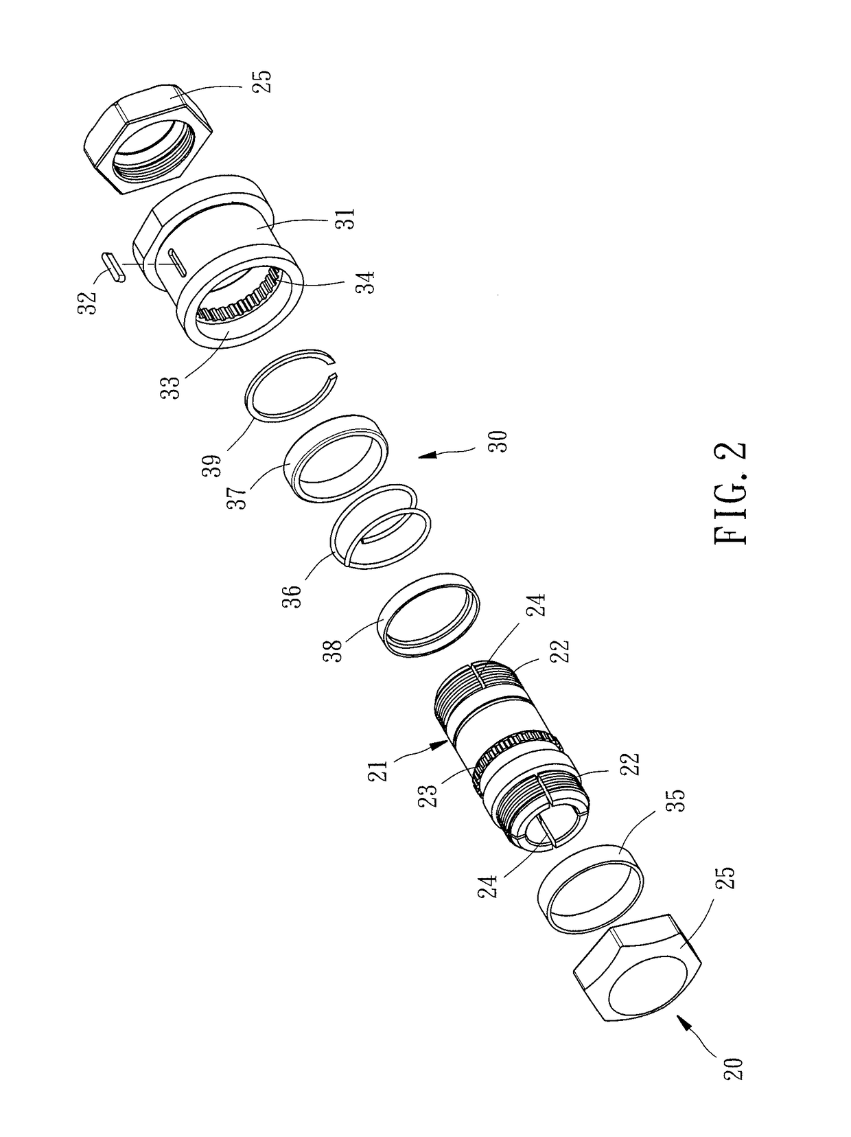
[0014]Referring to FIGS. 1 and 2, a handwheel clutch 100 for use in machinery in accordance with the present invention is shown. The handwheel clutch 100 comprises a handwheel mounting unit 20 and a clutch unit 30.

[0015]The handwheel mounting unit 20 comprises an axle sleeve 21 and two lock nuts 25. The axle sleeve 21 is adapted for attaching onto a handwheel axle 12 (see FIG. 3), comprising two outer thread portions 22 symmetrically located on two opposite ends thereof and an external toothed ring portion 23 extended around the periphery thereof and spaced between the two outer thread portions 22. The two lock nuts 25 are respectively threaded onto the two outer thread portions 22 of the axle sleeve 21. Thus, when fastening up the lock nuts 25 after sleeved the axle sleeve 21 onto the handwheel axle 12, the axle sleeve 21 and the handwheel axle 12 are locked together. Further, each outer thread portion 22 of the axle sleeve 21 has four longitudinal splits 24 (actually at least one ...


PUM


Abstract

A handwheel clutch includes a handwheel mounting unit including an axle sleeve with an external toothed ring portion and a lock nut threaded onto the axle sleeve, and a clutch unit including a clutch member with an internal toothed ring portion sleeved onto the axle sleeve and movable between a first position where the internal toothed ring portion is released from the external toothed ring portion for idle rotation of the clutch member relative to the axle sleeve and a second position where the internal toothed ring portion is meshed with the external toothed ring portion for allowing synchronous rotation of the axle sleeve with the clutch member.

Description

BACKGROUND OF THE INVENTION[0001]1. Field of the Invention[0002]The present invention relates to machinery technology and more particularly, to a handwheel clutch for use in machinery.[0003]2. Description of the Related Art[0004]When using a machine tool to drive a tool for machining a workpiece, the operator needs to manually drive a handwheel to rotate a handwheel axle, moving the worktable to an appropriate machining position. However, a conventional machine tool does not provide a clutch device between the handwheel and the handwheel axle. Thus, the handwheel can easily be collided by a surrounding staff, resulting in an offset of the worktable and affecting the machining accuracy.[0005]In order to solve the aforesaid problem, Taiwan Patent M492221 discloses a control device for controlling a clutch effect between an operating wheel and an axis tube. When pulls the control device, a plug rod will be moved with the control device axially to shift a plug rod, carrying a movable bl...

Claims


Application Information

Patent Timeline
Patent Type & Authority Applications(United States)
IPC IPC(8): F16D11/14F16D19/00F16D23/14
CPCF16D11/14F16D2011/002F16D19/00F16D23/14F16D1/0876F16D2001/0955F16D2011/004
Inventor CHANG, SHENG-FU
Owner FLAIR IND ACCESSORY
Why Eureka
Try Eureka