Spiral-flow type built-in cylindrical blast cap

A swirling and cylindrical technology, applied in the field of fluidized bed, can solve the problems of easy fluidization "dead zone" at the bottom of the bed, mutual erosion and wear of wind caps, poor fluidization uniformity, etc., to improve fluidization quality , prolong service life, convenient installation and maintenance

Active Publication Date: 2013-11-20
INST OF ENGINEERING THERMOPHYSICS - CHINESE ACAD OF SCI
View PDF1 Cites 0 Cited by
  • Summary
  • Abstract
  • Description
  • Claims
  • Application Information

AI Technical Summary

Problems solved by technology

[0005] The purpose of the present invention is to overcome the poor fluidization uniformity of the hood of the air distributor in the prior art, the fluidization "dead zone" is easy to appear at the bottom of the bed, and at the same time, there is serious mutual erosion and wear between the hoods, and the resistance of the hood is low And the general disadvantage of complex manufacturing process, through the special design of the hood structure, it provides a very simple structure and good fluidization performance, which can improve the gas-solid mixing intensity in the fluidized bed, improve combustion efficiency, and reduce the air between the hoods. Mutual flushing, anti-leakage slag swirling built-in cylindrical air cap to prolong the service life of the air cap

Method used


Image

  • Spiral-flow type built-in cylindrical blast cap
  • Spiral-flow type built-in cylindrical blast cap
  • Spiral-flow type built-in cylindrical blast cap

Examples


Embodiment 1

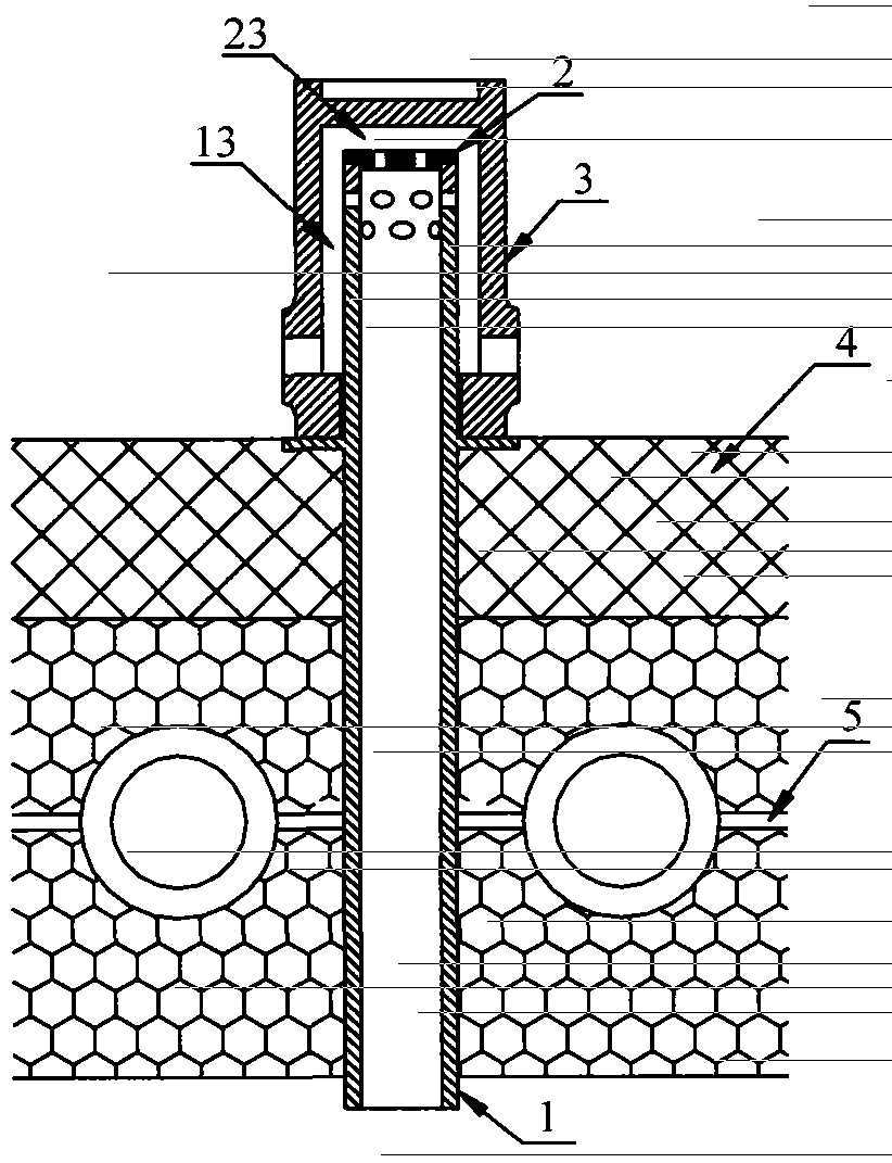
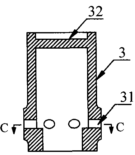
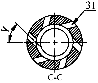
[0063] refer to figure 1 , 2 , 3, 4, 5, 6, 7 and 8, the present invention provides a swirl inlaid cylindrical air cap, which is composed of an inlaid pipe 1, a throttle block 2 and an outer sleeve 3. The inlaid pipe 1 is a straight pipe section with two open ends. The upper side wall of the inlaid pipe 1 is arranged with two layers of through holes 11 and 12 horizontally from the inside to the outside. The through holes 11 and 12 are counterclockwise along the inner wall of the inlaid pipe. The horizontal deflection angle α is 45°; the lower end of the outer casing 3 is open and the upper end is closed, and the side wall of the lower section of the outer casing 3 is provided with a through hole 31 horizontally arranged from the inside to the outside, and the through hole 31 along the inner wall of the outer casing clockwise horizontal deflection angle γ is: 45°, the outer casing 3 is coaxially buckled outside the inner tube 1, the inner diameter of the lower section of the ou...

Embodiment 2

[0066] refer to Figure 9 , 10 , 11 , 12 , 13 , 14 and 15 , the present invention provides a swirl-type embedded cylindrical hood, which is composed of an embedded tube 1 , a blind plate 2 ′ and an outer sleeve 3 . The inlaid pipe 1 is a straight pipe section with two open ends. The upper end side wall of the inlaid pipe 1 is arranged with two layers of through holes 11 and 12 horizontally from the inside to the outside. The through holes 11 and 12 are clockwise along the inner wall of the inlaid pipe. The horizontal deflection angle α is 30°; the lower end of the outer casing 3 is open, and the upper end is closed, and the side wall of the lower section of the outer casing 3 is provided with a through hole 31 horizontally arranged from the inside to the outside, and the through hole 31 along the inner wall of the outer casing. The horizontal deflection angle γ in the counterclockwise direction is 30°, the outer casing 3 is coaxially buckled outside the inner tube 1, the inne...

Embodiment 3

[0068] refer to Figure 16 , 17 , 18, 19, 20 and 21, the present invention provides a swirl in-line cylindrical hood, which consists of an in-line tube 1 and an outer sleeve 3 . The inlaid pipe 1 is a straight pipe section with two open ends. The upper end side wall of the inlaid pipe 1 is inclined downward from the inside to the outside to arrange the second-layer through holes 11 and 12, and the downward inclination angle δ is 15°. The through holes 11 and the through holes 12. The horizontal deflection angle α along the inner wall of the inner tube is 60° in the counterclockwise direction; the lower end of the outer tube 3 is open, and the upper end is closed, and the side wall of the lower section of the outer tube 3 is provided with through holes 31 horizontally arranged from the inside to the outside, and the through holes 31 are arranged along the inner surface of the outer tube. The horizontal deflection angle α of the wall in the clockwise direction is 60°, the outer...


PUM


Abstract

The invention discloses a spiral-flow type built-in cylindrical blast cap, which relates to a fluidized bed technology and comprises a built-in pipe and an outer sleeve pipe, wherein the built-in pipe is coaxially nested in the outer sleeve pipe, a circular seam is limited between the two pipes, the built-in pipe penetrates through and is fixed in an air distribution plate. The built-in pipe is in a straight pipe section with openings at two ends, the inner diameter of the lower end of the outer sleeve pipe is closely matched with the outer diameter of the built-in pipe, the side walls of the lower part of the outer sleeve pipe and the upper part of the built-in pipe are provided with through holes, the radial horizontal deflection angle of the projection of a central line of the through hole of the outer sleeve pipe on the horizontal plane and the side wall is identical to the radial horizontal deflection angle of the projection of a central line of the through hole of the built-in pipe on the horizontal plane and the side wall, the horizontal deflection directions are opposite, and the through hole of the outer sleeve pipe and the through hole of the built-in pipe are horizontally or downwards tiltedly arranged. According to the spiral-flow type built-in cylindrical blast cap disclosed by the invention, the fluidization uniformity of materials in a fluidized bed is improved, local fluidization dead zones at a bed bottom and corners are avoided, flushing abrasion between blast caps is reduced, the service life of the blast cap is prolonged, the blast cap resistance has a wide adjustment range, and the blast cap has a simple structure and is convenient to maintain.

Description

Field of Invention [0001] The invention relates to the technical field of fluidized beds, in particular to a swirling-type embedded cylindrical air cap used for an air distribution plate of a fluidized bed. technical background [0002] The air distribution device is one of the key components of the circulating fluidized bed boiler. Its performance directly affects the fluidization quality of the fluidized bed and the flow, reaction, heat and mass transfer in the fluidized bed, and then affects the entire furnace process. The air cap is the core component of the fluidized bed air distribution device. Its main function is to divert the air required for combustion twice, and generate strong disturbances on the upper part of the air cap, so that the fluidized air can be well mixed with the solid particles in the bed. make the combustion more complete. Under normal circumstances, the design requirements for the air cap meet: (1) It can distribute the airflow evenly and densely ...

Claims


Application Information

Patent Timeline
Patent Type & Authority Patents(China)
IPC IPC(8): F23C10/20
Inventor 宋国良孙运凯高鸣王东宇吕清刚
Owner INST OF ENGINEERING THERMOPHYSICS - CHINESE ACAD OF SCI
Why Eureka
Try Eureka