
Method for supplying air to telecommunication machine room and system

A communication equipment room, air supply technology, applied in heating and ventilation safety systems, heating and ventilation control systems, space heating and ventilation, etc., to achieve the effect of reducing cooling energy consumption

Inactive Publication Date: 2012-07-11
ZTE KANGXUN TELECOM COMPANY
View PDF5 Cites 15 Cited by
  • Summary
  • Abstract
  • Description
  • Claims
  • Application Information

AI Technical Summary

Problems solved by technology

[0003] The purpose of the present invention is to provide a method and system for air supply in a communication machine room, which is used to solve the local heat island in the machine room, ensure a stable temperature and humidity environment in the machine room, effectively use the outdoor cold source and greatly reduce the cooling energy consumption of the machine room

Method used


Image

  • Method for supplying air to telecommunication machine room and system
  • Method for supplying air to telecommunication machine room and system
  • Method for supplying air to telecommunication machine room and system

Examples


Embodiment Construction

[0048] The preferred embodiments of the present invention will be described in detail below in conjunction with the accompanying drawings. It should be understood that the preferred embodiments described below are only used to illustrate and explain the present invention, and are not intended to limit the present invention.

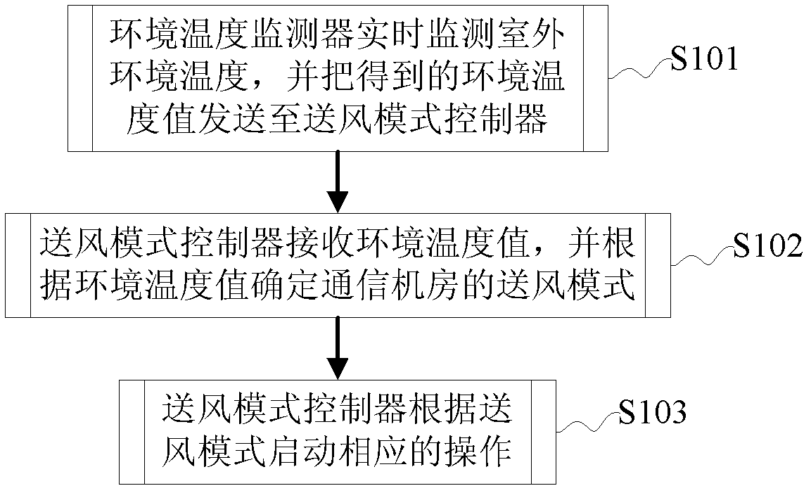
[0049] figure 1 Shows the schematic flow chart of the communication room air supply method provided by the present invention, as figure 1 Shown:

[0050] In step S101, the ambient temperature monitor monitors the outdoor ambient temperature in real time to obtain an ambient temperature value, and then sends the obtained ambient temperature value to the air supply mode controller.

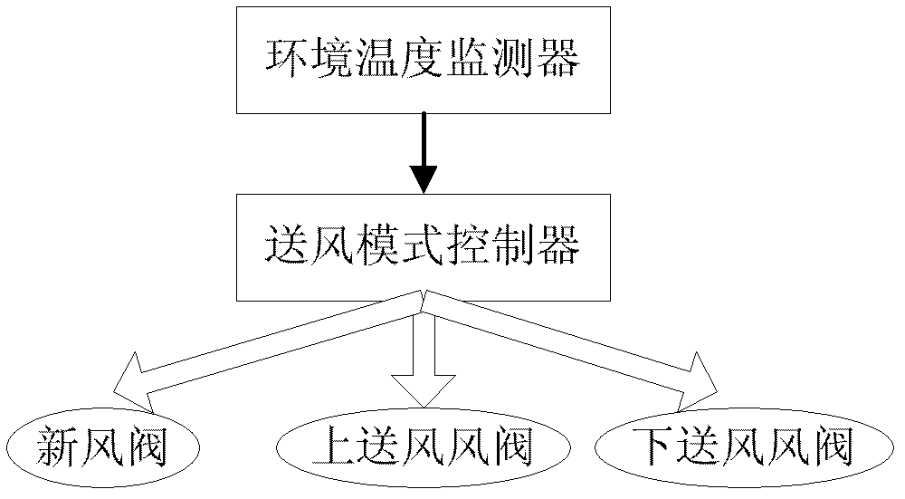
[0051] Step S102, the air supply mode controller receives the ambient temperature value, and determines the air supply mode of the communication room according to the ambient temperature value.

[0052] Wherein, the air supply mode controller presets the first to the third te...


PUM


Abstract

The invention discloses a method for supplying air to a telecommunication machine room and a system. The method includes that an ambient temperature monitor monitors outdoor ambient temperature in real time and transmits obtained ambient temperature values to an air supply mode controller; the air supply mode controller receives the ambient temperature values and determines an air supply mode of the telecommunication machine room according to the ambient temperature values; and the air supply mode starts corresponding operation according to the air supply mode. An environment with stable temperature and stable humidity in the machine room is realized by means of effectively utilizing an outdoor cold source and various air supply modes, and refrigeration energy consumption of the machine room is greatly reduced.

Description

technical field [0001] The invention relates to intelligent control technology, in particular to a method and system for air supply in a communication machine room. Background technique [0002] The communication industry is currently facing greater pressure to save energy and reduce emissions. Whether it is a small wireless base station computer room or a large and medium-sized computer room, the power consumption of the entire computer room is very huge. At present, most of the communication equipment rooms in China adopt an extensive equipment room thermal management mode. As a result, in the power consumption of the equipment room, the energy consumption for ventilation and cooling accounts for about 40% of the power consumption of the entire equipment room. In the direct air supply mode, the cooling capacity first cools the environment and then cools the equipment, resulting in a large waste of cooling energy consumption, and also causes local heat islands in the comput...

Claims


Application Information

Patent Timeline
Patent Type & Authority Applications(China)
IPC IPC(8): F24F11/00
Inventor 陈国强郭雨龙景佰亨靳世文朱敏波张萍
Owner ZTE KANGXUN TELECOM COMPANY
Learn More