Test system for engine driver display unit

A display unit and test system technology, which is applied in the transmission system, digital transmission system, railway vehicle test, etc., can solve the problems of energy waste and high test cost, and achieve the effect of saving test cost

Active Publication Date: 2012-07-11
CRRC DALIAN INST CO LTD
View PDF4 Cites 6 Cited by
  • Summary
  • Abstract
  • Description
  • Claims
  • Application Information

AI Technical Summary

Problems solved by technology

[0003] As an important equipment of locomotives, the driver display unit needs to be tested for performance before leaving the factory. If it is applied to the locomotive for testing, there will be a problem of high test cost and a waste of energy.

Method used


Image

  • Test system for engine driver display unit
  • Test system for engine driver display unit
  • Test system for engine driver display unit

Examples


Embodiment 1

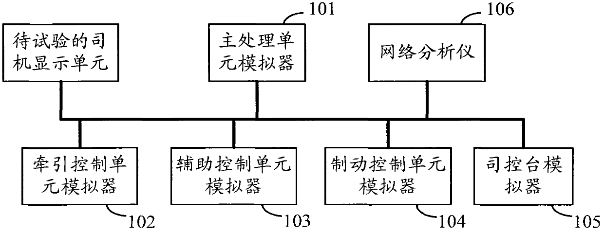
[0034] figure 1 A schematic structural diagram of the locomotive driver's display unit test system provided by Embodiment 1 of the present invention, as figure 1 As shown, the locomotive driver display unit test system includes: a main processing unit simulator 101 , a traction control unit simulator 102 , an auxiliary control unit simulator 103 , a brake control unit simulator 104 and a console simulator 105 . The main processing unit simulator 101 is used to encapsulate the main processing information data to form a data packet, and decapsulate the received data packet to simulate the main processing unit. The traction control unit simulator 102 is used to encapsulate the traction control information data to form a data packet, and decapsulate the received data packet to simulate the traction control unit. The auxiliary control unit simulator 103 is used to encapsulate the auxiliary control information data to form a data packet, and decapsulate the received data packet to ...

Embodiment 2

[0038] The locomotive driver display unit test system provided in this embodiment is based on Embodiment 1. The main processing unit simulator, the traction control unit simulator and the auxiliary control unit simulator can include an industrial computer and an acquisition card respectively, and the acquisition card is plugged in In the industrial computer, the industrial computer is used to process, store and process data, and the acquisition card is used to encapsulate the data processed by the industrial computer to form a data packet, and decapsulate the received data packet, and provide it to the industrial computer for processing . The brake control unit simulator and the console simulator respectively include a central processing unit and a mainboard card, and the central processing unit is inserted on the mainboard card. The industrial computer has stable performance, can adapt to the requirements of the locomotive movement environment, and improves the accuracy of th...


PUM


Abstract

The invention provides atest system for an engine driver display unit. The system comprises a main processing unit simulator, a traction control unit simulator, an auxiliary control unit simulator, a brake control unit simulator and an engine driver console simulator, wherein the main processing unit simulator, the traction control unit simulator, the auxiliary control unit simulator, the brake control unit simulator and the engine driver console simulator are mutually connected through a factory instrument protocol vehicle network so as to simulate engine equipment and package the generated simulated data into a data packet which is then sent to a to-be-tested engine driver display unit connected to the factory instrument protocol vehicle network. The test system for the engine driver display unit, provided by the invention, is used for simulating the engine equipment to carry out data interaction with the engine driver display unit through the arrangement of the main processing unit simulator, the traction control unit simulator, the auxiliary control unit simulator, the brake control unit simulator and the engine driver console simulator, so that the ground test property of the engine driver display unit is realized.

Description

technical field [0001] The invention relates to a structure technology of a locomotive equipment test system, in particular to a locomotive driver display unit test system. Background technique [0002] The control systems of modern high-power AC drive electric locomotives are all based on the network structure, and the World FIP (World Factory Instrumentation Protocol, World FIP for short) network is one of the networks. The World FIP network is divided into a vehicle network and a train network. The vehicle network is mainly used for information exchange between the internal equipment of a single locomotive. The internal equipment of the locomotive usually includes: driver display unit, main control unit, traction control unit, auxiliary control unit, brake control unit and driver console. The main function of the driver display unit is to capture and collect periodic process data, non-periodic process data and non-periodic message data of other equipment inside the locom...

Claims


Application Information

Patent Timeline
Patent Type & Authority Applications(China)
IPC IPC(8): G01M17/08H04L12/26
Inventor 关颖王昌荣
Owner CRRC DALIAN INST CO LTD
Why Eureka
Try Eureka