Flat plate fatigue bending machine

A bending fatigue, testing machine technology, used in the testing of mechanical parts, the testing of machine/structural parts, the use of repetitive force/pulse force to test the strength of materials, etc., can solve the problem of high cost, complex control system and large size of the detector and other problems, to achieve the effect of low power consumption, simple control system and high detection accuracy

Inactive Publication Date: 2008-09-24
GUANGXI UNIVERSITY OF TECHNOLOGY
View PDF1 Cites 48 Cited by
  • Summary
  • Abstract
  • Description
  • Claims
  • Application Information

AI Technical Summary

Problems solved by technology

However, the detector described in this document has a larger

Method used


Image

  • Flat plate fatigue bending machine
  • Flat plate fatigue bending machine
  • Flat plate fatigue bending machine

Examples


Embodiment 1

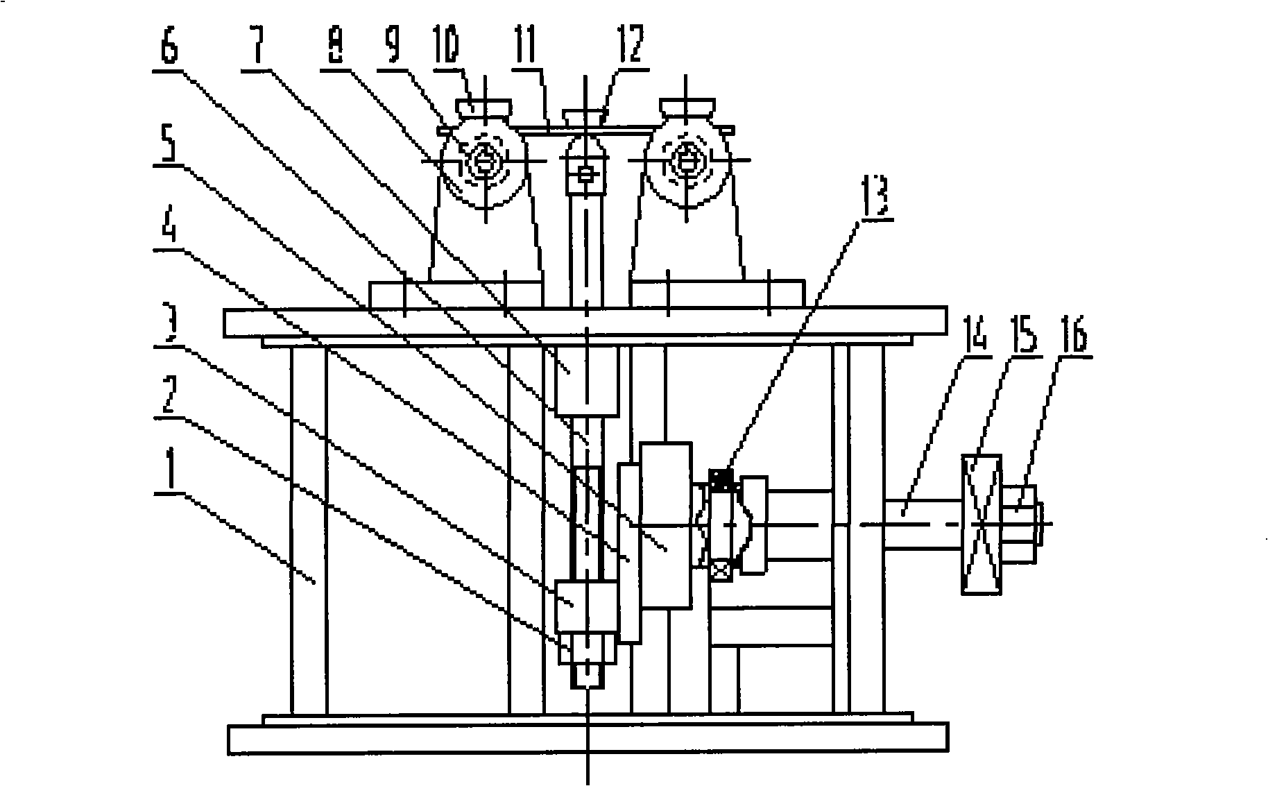
[0021] Embodiment 1: Complete the three-point bending fatigue test. as attached figure 2 As shown, the mechanical device of the present invention includes a frame 1, a locknut 2, a connecting rod hinge block 3, a connecting rod 4, an eccentric wheel 5, a driving rod 6, a chute (rail) 7, a clamp support seat 8, and a bearing 9 , Fixture 10, test piece 11, test piece splint 12, bearing 13, rotating shaft 14, gear 15, nut 16. The frame 1 is placed on the test field, the driving rod 6 is fixed on the chute (guide rail) 7, and the lower end is fastened with the locknut 2, and the shaft 14 is equipped with a bearing 13, a gear 15 and a nut 16, which are installed on the frame 1 The side of the test piece 11 is installed between the fixtures 10 with the test piece splint 12. The fixture support seat 8 and the bearing 9 are arranged on the fixture 10. The driving rod 6 and the rotating shaft 14 are hinged with the eccentric wheel 5 through the connecting rod 4.

Embodiment 2

[0022] Embodiment 2: Complete the cantilever bending fatigue test. as attached image 3 As shown, the present invention comprises, frame 1, lock nut 2, connecting rod hinged block 3, connecting rod 4, eccentric wheel 5, driving rod 6, chute (guide rail) 7, test piece splint 17, test piece 18, Fixture 19, bearing seat 11, bearing 12, rotating shaft 13, gear 14, nut 15, frame 1 is placed on the test field, driving rod 6 is fixed on chute (guide rail) 7, the lower end is fastened with lock nut 2, and the rotating shaft Bearing 13, gear 15 and nut 16 are installed on 14, and they are installed on the side of frame 1, and test piece 18 is installed between fixture 19 with test piece splint 17, and driving rod 6 and rotating shaft 14 pass connecting rod 4 and eccentric wheel 5 hinged.

[0023] When performing the bending fatigue test: install the flat specimen on the fixture, the rotating shaft 13 drives the eccentric wheel 5 to rotate, and the connecting rod 4 connected with the ...


PUM


Abstract

A small flat bending fatigue test machine can dynamically monitor and test the fatigue of a specimen (material) and is based on an acoustic emission technology. The machine includes a plurality of parts, such as a mechanical device, a loading device, a tester, a display or recording device, etc. The mechanical device and the loading device are integrated and adopt an eccentric wheel rotating mechanism and a dynamic loading method; the tester includes two parts, namely a load test system and a specimen test system; the load test system consists of a limit switch, an electronic accumulation calculator, etc.; the specimen test system adopts an acoustic emission sensing electronic technology and a computer technology; the specimen is arranged on the mechanical device and the loading device; the loading device pressurizes the specimen on the mechanical device; the specimen is provided with an acoustic emission sensor; the acoustic sensor is connected with a load tester; the signal is input into the computer technology, and the display or record device obtains the bending fatigue test result of the material.

Description

technical field [0001] The invention relates to performance testing equipment for metal materials, in particular to a bending fatigue testing machine. Background technique [0002] Fatigue damage is one of the main forms of failure of mechanical equipment parts. At present, the effective way to prevent fatigue damage is to conduct fatigue tests to estimate the fatigue life of moving parts, so as to determine the service life of machines and parts. Fatigue testing machine is an indispensable equipment in the study of material fatigue performance. So many people have designed the bending fatigue testing machine, such as the Chinese patent: "Superimposed Load Rotating Bending Fatigue Testing Machine" (application number: 87210621), which consists of a high-frequency low-amplitude loading mechanism, a low-frequency lever enamel loading mechanism and a machine base , spindle box, chuck, test piece corrosion box and motor and other components. It can carry out the fatigue test o...

Claims


Application Information

Patent Timeline
IPC IPC(8): G01N3/34G01M13/00
Inventor 毛汉颖毛汉领曾德良黄振峰范健文吴彤峰李晓萍
Owner GUANGXI UNIVERSITY OF TECHNOLOGY
Why Eureka
Try Eureka