Power cable fault location method based on transfer function method

A transfer function and power cable technology, which is applied in the field of power cable fault location based on the transfer function method, can solve the problems of waveform amplitude attenuation, traveling wave signal scattering, waveform width widening, etc., and achieve positioning measurement errors and limitations Small, easy to operate, good effect

Active Publication Date: 2012-07-11
ELECTRIC POWER RES INST OF GUANGDONG POWER GRID
View PDF3 Cites 22 Cited by
  • Summary
  • Abstract
  • Description
  • Claims
  • Application Information

AI Technical Summary

Problems solved by technology

[0003] 1. The traveling wave signal will be scattered and diffracted during the transmission of the cable
[0004] 2. Due to the dielectric loss and transmission ...

Method used


Image

  • Power cable fault location method based on transfer function method
  • Power cable fault location method based on transfer function method
  • Power cable fault location method based on transfer function method

Examples


Embodiment Construction

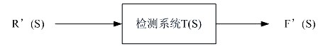
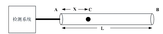
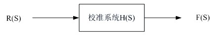
[0041] Such as Figure 1 to Figure 3 Shown embodiment of the present invention, the present invention is based on the power cable fault localization method of transfer function method, comprises the following several steps:

[0042] S1 : see figure 1 , input a low-voltage calibration pulse signal from one end of the power cable through the measuring device, collect and save the reflected calibration original pulse and calibration reflected pulse, and obtain the calibration transfer function of the calibration model; The connecting cable is connected, so the pulse signal input through the measuring device will produce reflection and refraction of the waveform at the near end and the far end of the cable: at the near end due to the impedance mismatch between the connecting cable and the test cable, reflection occurs and then transmitted back The reflected signal of the measuring device is the original pulse r(t), and the reflected signal transmitted back to the measuring devi...


PUM


Abstract

The invention discloses a power cable fault location method based on a transfer function method, which particularly comprises that, the transfer function method obtains fault information of power cables by multiple inputs of voltage signals, the fault information includes calibrating signals and test signals, a transfer function of a circuit calibrating equivalent model is found through related technologies of signals and signal processing, original pulse is regarded as input signals in the equivalent model, reflected pulse is regarded as output signals, and the transfer function of the equivalent model is obtained. Wave speed and power cable length are known, so that fault locations of power cables are determined. The method for treating the fault information is low in cost and convenient to operate, and accurate location is achieved through related algorithm.

Description

technical field [0001] The invention relates to a power cable fault location technology, in particular to a power cable fault location method based on a transfer function method. Background technique [0002] With the expansion of the scale of my country's power grid and the construction of various large-scale power projects, high-voltage power cable lines have been widely used. The diagnosis and search of power cable faults is also an important issue in the current power construction. The commonly used method to obtain the time difference is usually to measure the time of a certain point with characteristics of the signal, and then directly subtract the corresponding time of different receiving points get. In the prior art, using the above method of obtaining the time difference, the traveling wave method applied to power cable fault location mainly includes the single-ended traveling wave method and the double-ended traveling wave method. For the single-ended traveling wa...

Claims


Application Information

Patent Timeline
IPC IPC(8): G01R31/11
Inventor 喇元田立斌叶加骅
Owner ELECTRIC POWER RES INST OF GUANGDONG POWER GRID
Why Eureka
Try Eureka