Detection method of LED (light-emitting diode) lamp array

A detection method and technology of LED lights, applied in the field of LED light array detection, can solve the problems of poor continuous welding of LED light arrays and achieve 100% effective detection, and achieve the goals of less visual fatigue, convenient detection of false welding, and convenient continuous welding detection Effect

Inactive Publication Date: 2012-07-11
晨讯科技(沈阳)有限公司
View PDF0 Cites 2 Cited by
  • Summary
  • Abstract
  • Description
  • Claims
  • Application Information

AI Technical Summary

Problems solved by technology

[0005] The technical problem to be solved by the present invention is to overcome the defect that the existing technology cannot realize 100% effective detection of the defective continuous welding of the LED lamp array, and provide a method that can realize 100% effective detection and detection process of the defective continuous welding of the LED lamp array. LED light array inspection method that is fast and does not easily cause visual fatigue to inspectors

Method used


Image

  • Detection method of LED (light-emitting diode) lamp array
  • Detection method of LED (light-emitting diode) lamp array
  • Detection method of LED (light-emitting diode) lamp array

Examples


Embodiment Construction

[0020] The preferred embodiments of the present invention are given below in conjunction with the accompanying drawings to describe the technical solution of the present invention in detail.

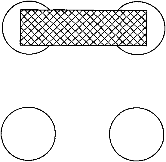
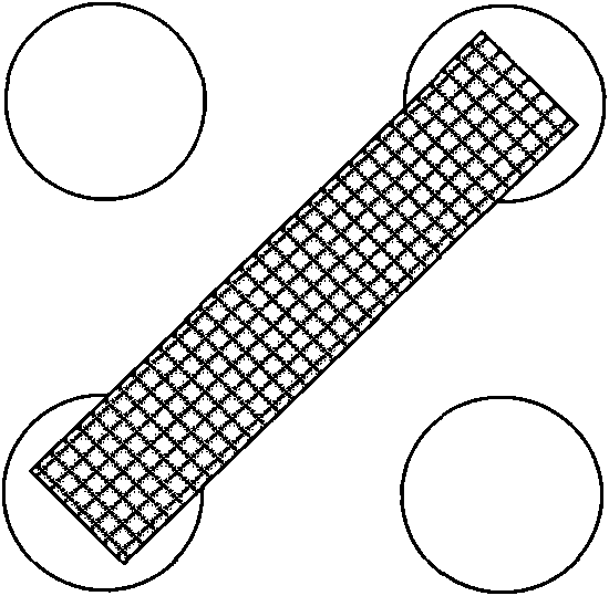
[0021] When there is poor connection between various pins on the driver chip of the LED light array, there may be two continuous welding states: figure 1 Adjacent bonding as shown, that is, bonding occurs between two laterally or vertically adjacent leads; and, if figure 2 The diagonal joint welding shown is that the joint welding occurs between two adjacent pins along the diagonal direction.

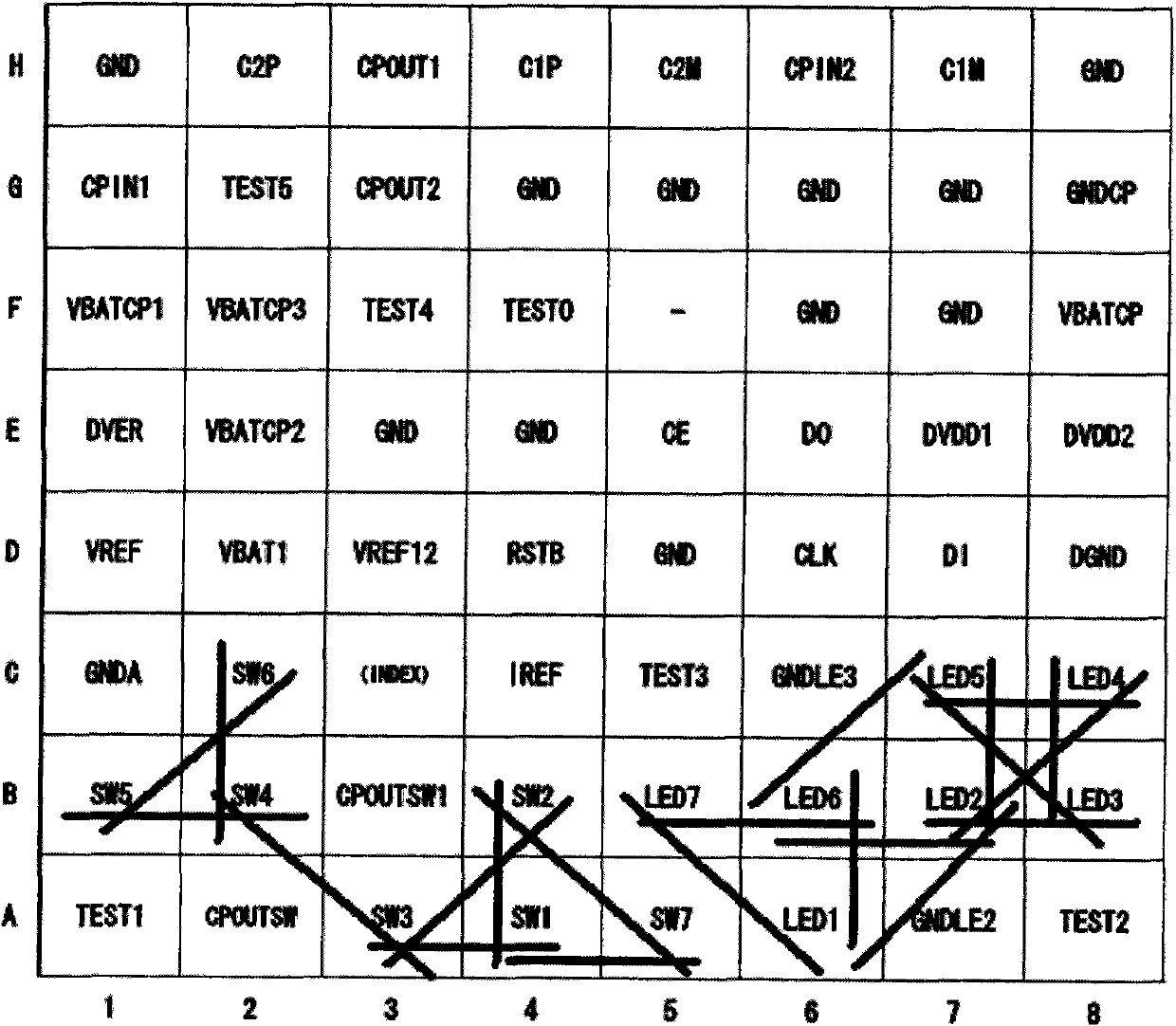
[0022] Through the functional analysis of various pins, it can be seen that only the welding between the driving pins of the LED (including the positive pin and the negative pin) will be reflected in the display state of the LED light array, and the LED The welding connection between the driving pin and other functional pins can be effectively detected in other existing functional testing proced...


PUM


Abstract

The invention discloses a detection method of an LED (light-emitting diode) lamp array. The detection method comprises the following steps: S1) determining the possibility of continuous welding on a driving chip; S2) determining associated pins of each LED; S3) selecting one LED from the LEDs with the maximum number of the associated pins as the LED for detection; S4) selecting one LED from the LEDs with the maximum number of the associated pins which are not repeated with the associated pins of all the selected LEDs for detection; S5) repeatedly implementing the step S4) till the possibility of continuous welding of all the selected LEDs for detection covers all the possibility of the continuous welding, which is determined in the S1); S6) turning on all the LEDs and judging whether all the LEDs are normally turned on or not; and S7) only turning on all the LEDs for detection and judging whether only the LEDs for detection in the LED lamp array are turned on or not. According to the detection method disclosed by the invention, effective detection on poor continuous welding can be realized by 100%, the test speed is very fast, and the detection method is less prone to causing visual fatigue of test staff.

Description

technical field [0001] The invention relates to a method for detecting an LED lamp array. Background technique [0002] LED light arrays are widely used in many fields. For example, LED light arrays are installed on the outer screens of some mobile phones to display different patterns or numbers in different functional occasions of the mobile phone. [0003] The existing LED light array test procedure is generally divided into two steps: Step 1, light up all the LEDs in the LED light array to detect the virtual soldering of the driver chip of the LED light array; Step 2, according to a certain display pattern point Light up some LEDs in the LED light array, for example, according to the order of all odd-numbered column LEDs->all even-numbered column LEDs->all odd-numbered row LEDs->all even-numbered row LEDs in sequence to light up some LEDs in order to detect the connection of the driver chip. [0004] In such a test program, although the effective detection of th...

Claims


Application Information

Patent Timeline
Patent Type & Authority Applications(China)
IPC IPC(8): G01R31/44G01R31/02
Inventor 黄训刚石翠娥
Owner 晨讯科技(沈阳)有限公司
Why Eureka
Try Eureka