
Bidirectional optical sub assembly having structure to reduce reflection noise

A technology of reflecting noise and bidirectional light, applied in bidirectional transmission, optical components, optics, etc., can solve the problem of high cost

Active Publication Date: 2012-07-11
OPTOELECTRONICS SOLUTIONS
View PDF5 Cites 2 Cited by
  • Summary
  • Abstract
  • Description
  • Claims
  • Application Information

AI Technical Summary

Problems solved by technology

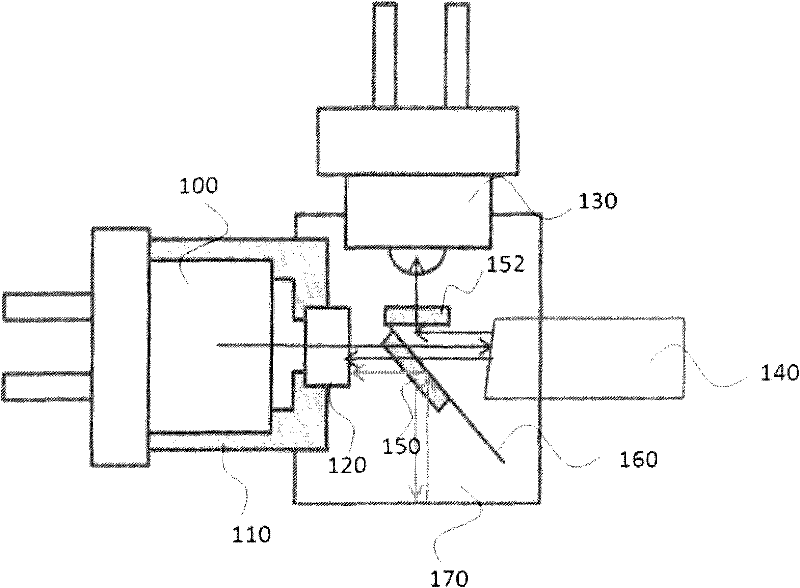
[0008] However, the isolator 120 is an expensive optical device, and the BOSA module equipped with the isolator not only costs high, but also causes additional manufacturing processes

Method used


Image

  • Bidirectional optical sub assembly having structure to reduce reflection noise
  • Bidirectional optical sub assembly having structure to reduce reflection noise
  • Bidirectional optical sub assembly having structure to reduce reflection noise

Examples


Embodiment Construction

[0032] Preferred embodiments will be described in detail with reference to the accompanying drawings.

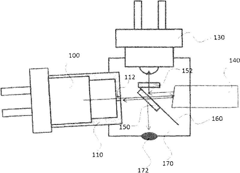
[0033] figure 2 A schematic diagram showing a bidirectional light assembly according to a preferred embodiment of the present invention. refer to figure 2 , the bi-directional optical assembly with a reflection noise reduction structure may include: a transmitter 100, a cover 110, an opening 112, a receiver 130, an optical fiber 140, filters 150 and 152, a filter holder 160, a body 170, and an absorber 172.

[0034] The transmitter 100 outputs and transmits an optical transmission signal through the optical fiber 140 . Transmitter 100 may include a laser diode (LD).

[0035] The cover 110 is used to surround the transmitter 100 and may include an opening 112 for passage of an optical transmission signal from the transmitter 100 to be transmitted to the optical fiber 140 .

[0036] The opening 112 serves as a passage for the optical transmission signal from the transmi...


PUM


Abstract

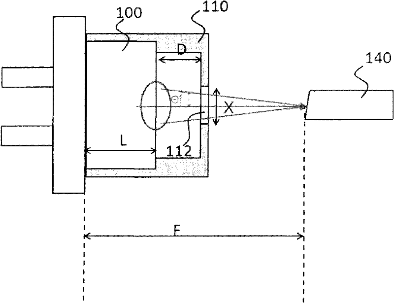
Disclosed herein is a bi-directional optical sub-assembly structured to reduce reflection noise. The bi-directional optical sub-assembly includes an optical fiber; a transmitter transmitting an optical transmit signal having passed through a 45 DEG filter to the outside through the optical fiber, a receiver receiving an optical receive signal which is received from the outside through the optical fiber, is reflected by the 45 DEG filter and passes through a 0 DEG filter; a body encompassing a part of the optical fiber, a part of the transmitter and a part of the receiver; a cap housing encompassing a part of the transmitter and including an opening to provide a passage for the optical transmit signal from the transmitter to the optical fiber, and a filter holder having the 45 DEG filter and the 0 DEG filter attached thereon within the body. The opening of the cap housing is set to have a minimum diameter Xmin and a maximum diameter Xmax so as to transmit the optical transmit signal without loss and to prevent the optical transmit signal from entering back to the transmitter after the optical transmit signal is reflected by the optical fiber, and the filter holder includes a first passage connected to the 45 DEG filter and a second passage connected to the 0 DEG filter. The first passage is set to have a predetermined filter holder size dh so as to prevent the optical transmit signal from entering the receiver after the optical transmit signal is reflected by the optical fiber.

Description

technical field [0001] The present invention relates to a bidirectional optical component, and more particularly, to a bidirectional optical component with a structure that reduces noise generated by light reflection therein, so as to reduce signal distortion. Background technique [0002] In fiber optic communications, a transceiver typically includes a transmitter using a laser diode (LD) and a receiver using a photodiode (PD). Recently, separate entities called two-way transceivers, which incorporate a transmitter and a receiver inside, have been widely used. A bidirectional optical assembly (BOSA) refers to a structure equipped with a bidirectional transceiver as a main component. [0003] figure 1 Schematic showing a conventional bidirectional optical assembly (BOSA). refer to figure 1 , the BOSA includes a transmitter 100 , a cap housing 110 , an isolator 120 , a receiver 130 , an optical fiber 140 , an optical filter 150 , an optical filter holder 160 and a body 1...

Claims


Application Information

Patent Timeline
Patent Type & Authority Applications(China)
IPC IPC(8): G02B6/42H04B10/24
CPCG02B6/4246H04B10/2503G02B6/4207H04B10/40H04B10/2589
Inventor 黄美熙申东镇尹奭汉郑银教
Owner OPTOELECTRONICS SOLUTIONS
Learn More