Clamping die for heat sealing of lead acid storage battery case cover

A lead-acid battery, clamping mold technology, applied in lead-acid battery, lead-acid battery construction, battery pack parts and other directions, can solve the problems of reduced battery capacity, low assembly pressure, large self-discharge, etc., to achieve easy mold processing , The effect of high heat sealing efficiency and simple structure

Inactive Publication Date: 2012-07-11
JIANGSU LEOCH BATTERY
View PDF5 Cites 0 Cited by
  • Summary
  • Abstract
  • Description
  • Claims
  • Application Information

AI Technical Summary

Problems solved by technology

[0002] In the production process of VRLA maintenance-free automotive batteries, there is a heat-sealing process for the battery cover. , the assembly is tight, and the battery case is made of soft PP material, so the mouth of the battery case with the electrode group will open outward under the pressure of the electrode group, which will often cause the case cover to be dislocated and poorly sealed during heat sealing. , and eventually the battery was scrapped due to poor heat sealing
In order to solve this problem, it is usually to reduce the assembly pressure so that the battery shell does not deform. This method has the following problems: 1. The assembly pressure is low, the battery has poor discharge performance at high currents, acid stratification is prone to occur, and self-discharge is large; 2. 1. In order to reduce the assembly pressure, the thickness of the separator has to be reduced. The thickness of the separator is reduced, and the separator is easy to be damaged, so that the phenomenon of short circuit of the battery increases; 3. The separator itself is designed to be thinner, and the separator can not be thinned. Therefore, the number or thickness of the plates has to be reduced, which will reduce the capacity of the battery

Method used


Image

  • Clamping die for heat sealing of lead acid storage battery case cover
  • Clamping die for heat sealing of lead acid storage battery case cover

Examples


Embodiment Construction

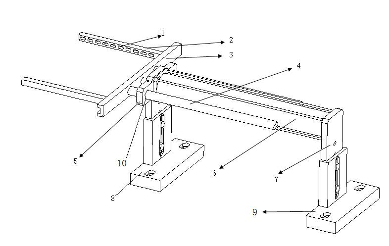
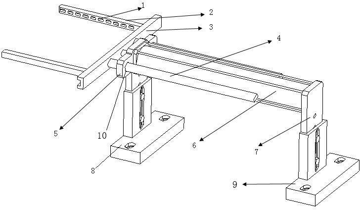
[0011] Such as figure 1 As shown, the clamping mold includes a fastening arm 2, a connecting block 3, a front support plate 5, a cylinder 6, a rear support plate 7, a front base 8 and a rear base 9, and the front base 8 is installed with the front support plate by adjusting bolts 5. Install the cylinder 6 between the rear support plate 7, the front support plate 5 and the rear support plate 7 on the rear base 9, install the connecting block 3 on the ejector rod of the cylinder 6, and install on both ends of the connecting block 3 The fastening arm 2 constitutes a clamping die as a whole.

[0012] Wherein, rollers 1 are distributed on the inner wall of the fastening arm 2 .

[0013] Wherein, the connecting block 3 is respectively connected with a sliding rod 4 on both sides of the ejector rod of the cylinder, and the sliding rod 4 is inserted into the sliding rod installation hole 10 on the front support plate 5 .

[0014] When installing, the front base 8 and the rear base 9...


PUM


Abstract

The invention discloses a clamping die for heat seal of a lead acid storage battery case cover. The clamping die comprises fastening arms (2), a connection block (3), a front support plate (5), a cylinder (6), a rear support plate (7), a front base (8) and a rear base (9), wherein the front support plate (5) is mounted on the front base (8) through adjusting bolts, the rear support plate (7) is mounted on the rear base (9) through adjusting bolts, the cylinder (6) is mounted between the front support plate (6) and the rear support plate (7), the connection block (3) is mounted on an ejector rod of the cylinder (6), and the fastening arms (2) are mounted at two ends of the connection block (3), therefore, an integral clamping die is formed. In the invention, the clamping die is used for fixing the shape of a battery case, so as to enable the battery case to keep the original shape during heat sealing, a battery cover is enabled to be aligned with the hot-melting rib of the battery case, after smelting, the battery cover and the hot-melting rib of the battery case are tightly bonded together, the clamping assembly of the battery is kept, poor heat sealing is reduced, the difficulty in heat sealing is lowered, the heat-seal efficiency is improved, and the aesthetics of the battery after heat seal is improved.

Description

technical field [0001] The invention relates to a jig for heat-sealing the shell cover of a lead-acid battery, in particular to a clamping die for heat-sealing the shell cover of a lead-acid battery. Background technique [0002] In the production process of valve-controlled sealed lead-acid battery maintenance-free automotive batteries, there is a battery cover heat-sealing process. In this process, the battery cover and battery shell are sealed together by a heat-sealing machine. Since maintenance-free automotive batteries are used for high-current discharge , the assembly is tight, and the battery case is made of soft PP material, so the mouth of the battery case with the electrode group will open outwards under the pressure of the electrode group, which will often cause the case cover to be misplaced and poorly sealed during heat sealing. , and eventually the battery was scrapped due to poor heat sealing. In order to solve this problem, it is usually to reduce the assem...

Claims


Application Information

Patent Timeline
Patent Type & Authority Applications(China)
IPC IPC(8): H01M10/12H01M2/02
CPCY02E60/126Y02E60/10Y02P70/50
Inventor 彭小勐张守君
Owner JIANGSU LEOCH BATTERY
Why Eureka
Try Eureka