Automatic retraction device and extension guide

A pull-out guide device and automatic technology, which is applied to switches with brake parts, door/window accessories, wing parts, etc., can solve the problems of complicated installation of driving parts, and achieve reliable and fast small space effect

Active Publication Date: 2012-07-11
PAUL HETTICH
View PDF7 Cites 3 Cited by
  • Summary
  • Abstract
  • Description
  • Claims
  • Application Information

AI Technical Summary

Problems solved by technology

In known structures of said type, the installation of the driver is also very complicated

Method used


Image

  • Automatic retraction device and extension guide
  • Automatic retraction device and extension guide
  • Automatic retraction device and extension guide

Examples


Embodiment Construction

[0024] In the following description of the figures, concepts such as up, down, left, right, front, rear etc. relate only to selected exemplary illustrations and positions of devices and other parts in the current figure. These terms are not to be understood restrictively, ie these positional relationships may change due to different operating states and / or a mirror-symmetrical design or the like.

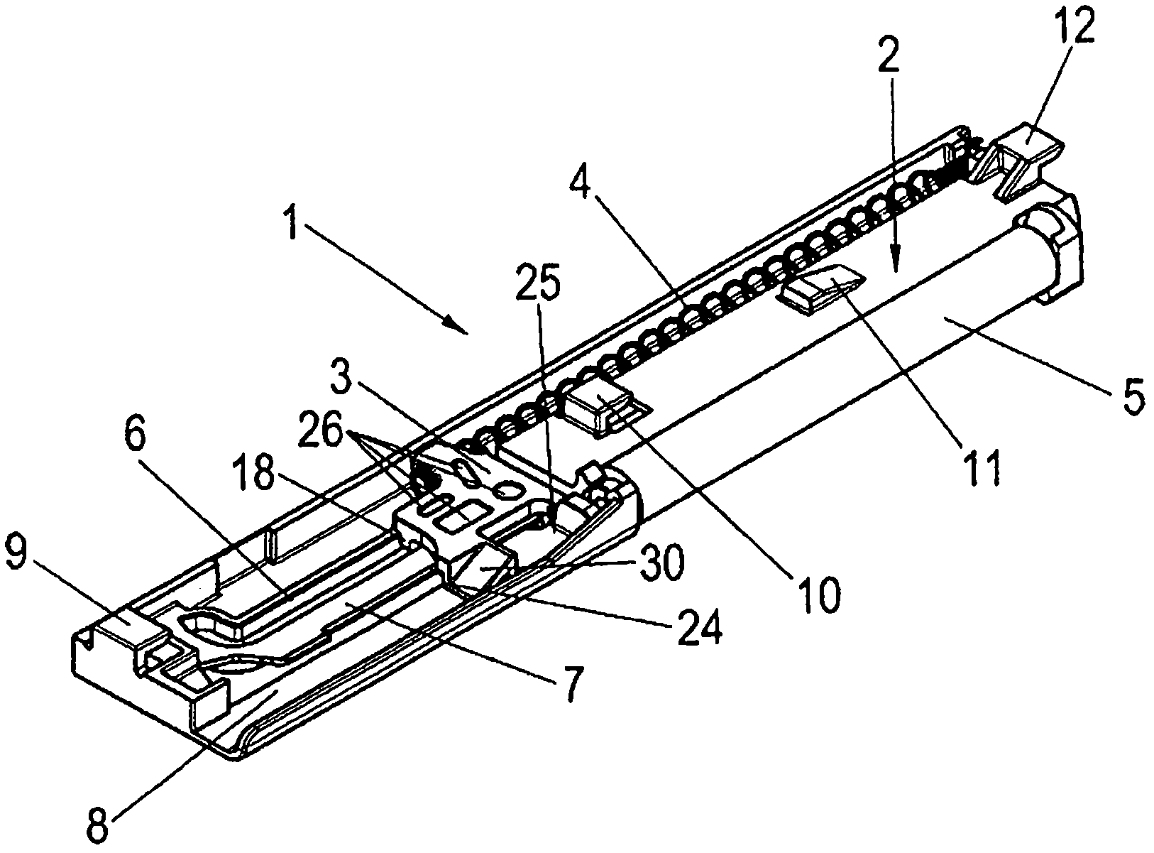
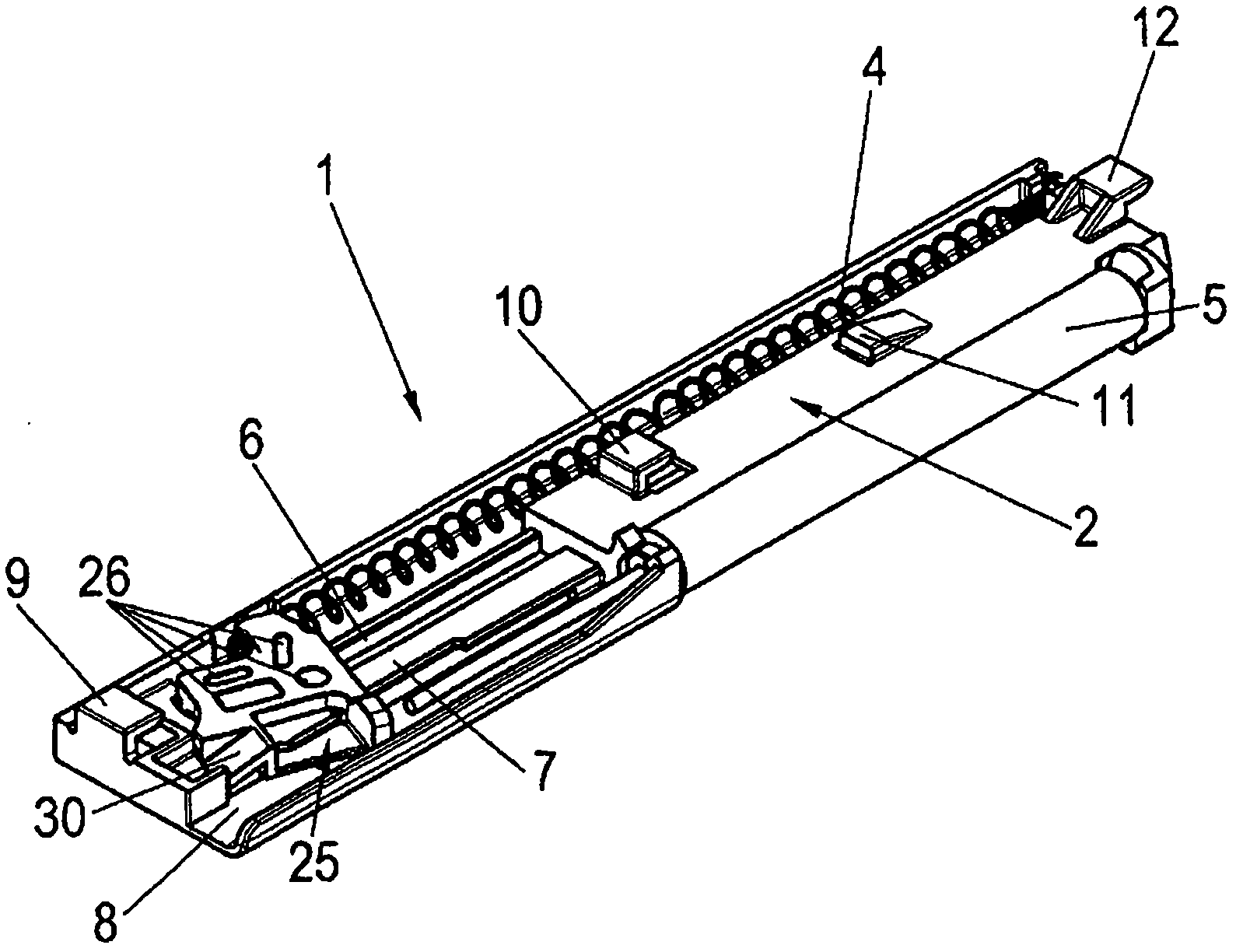
[0025] figure 1 and 2 The reference numeral 1 generally designates an automatic pull-in device, which is connected to the pull-out guide 32 in the Figure 6 and 7 Controlled by an actuator 20 on a slide rail 21 shown in . The pull-out guide device 32 may have a guide rail 22 that can be fixed on the furniture body, a slide rail 21 that can move on the guide rail, and an intermediate rail arranged between the guide rail and the slide rail.

[0026] The automatic retraction device 1 essentially comprises a housing 2 , into which an energy store 4 is inserted, which is preferably d...


PUM


Abstract

An automatic retraction device (1) for a movable furniture part guided by an extension rail, having a housing (2), a force accumulator (4) which is arranged on the housing (2) and can be tensioned during the opening of the movable furniture part, and a tensioning mechanism which is operatively connected to the force accumulator (4) and is intended for pretensioning the force accumulator (4) by means of a carrier (3) arranged displaceably on the housing (2), the housing (2) having a sliding rail (7) on which the carrier (3) can be mounted.

Description

technical field [0001] The invention relates to an automatic pull-in device for movable furniture parts guided by pull-out rails according to the preamble of claim 1 and to a drawer, furniture puller according to the preamble of claim 9 Pull-out guide with automatic pull-in device for output pieces or the like. Background technique [0002] Various configurations of automatic pull-in devices and pull-out guides of the above-mentioned type are known from the prior art. The automatic pull-in device here mainly consists of an energy accumulator arranged on a housing fixed on a guide rail fixed to the furniture body, wherein when a drawer, a furniture pull-out or the like is pulled out from the closed position For objects, the energy accumulator is tensioned by coupling the automatic pull-in device with the actuator, wherein the actuator is fastened to a slide rail which itself is fastened to a drawer, a furniture pull-out or the like and Able to move on rails. [0003] In kn...

Claims


Application Information

Patent Timeline
Patent Type & Authority Applications(China)
IPC IPC(8): A47B88/04
CPCE05F5/003E05Y2201/488A47B88/047E05F1/16E05Y2800/24E05F5/027A47B88/467E05Y2201/412E05Y2900/20
Inventor S・克劳斯
Owner PAUL HETTICH
Why Eureka
Try Eureka