
Tool for placing a joint in a leaf rebate of a vehicle

A joint body and tool technology, applied in the manufacture of tools, vehicle parts, metal processing, etc.

Inactive Publication Date: 2012-07-11
PEZHO SITROEN AUTOMOBILS SA
View PDF7 Cites 1 Cited by
  • Summary
  • Abstract
  • Description
  • Claims
  • Application Information

AI Technical Summary

Problems solved by technology

This prior art tool therefore cannot meet the requirement

Method used


Image

  • Tool for placing a joint in a leaf rebate of a vehicle
  • Tool for placing a joint in a leaf rebate of a vehicle
  • Tool for placing a joint in a leaf rebate of a vehicle

Examples


Embodiment Construction

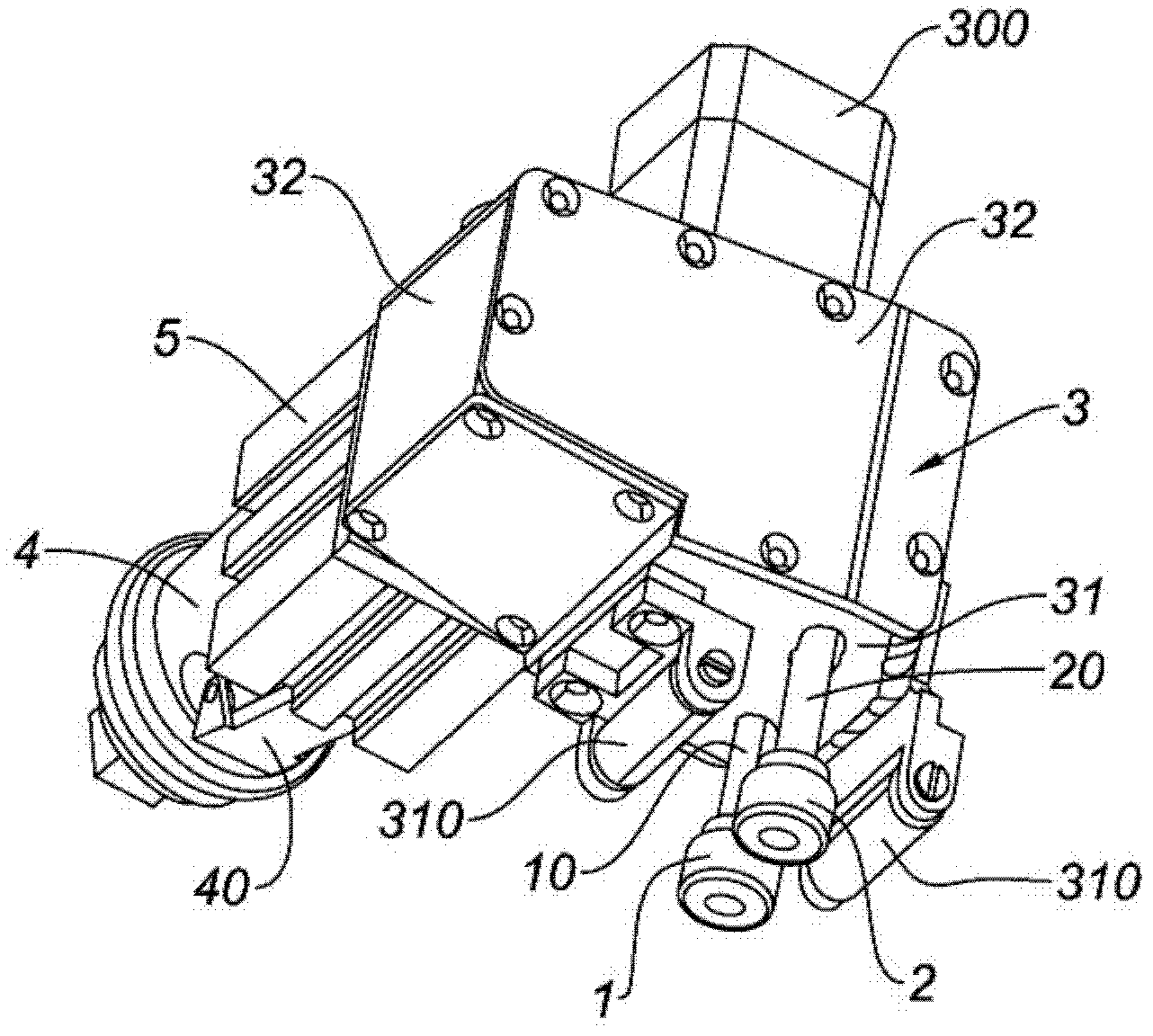
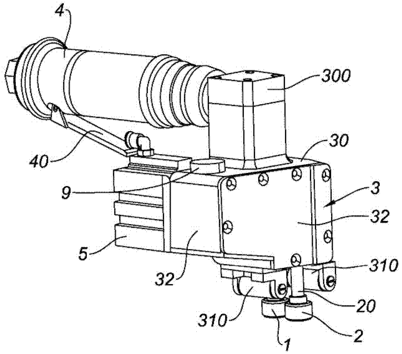
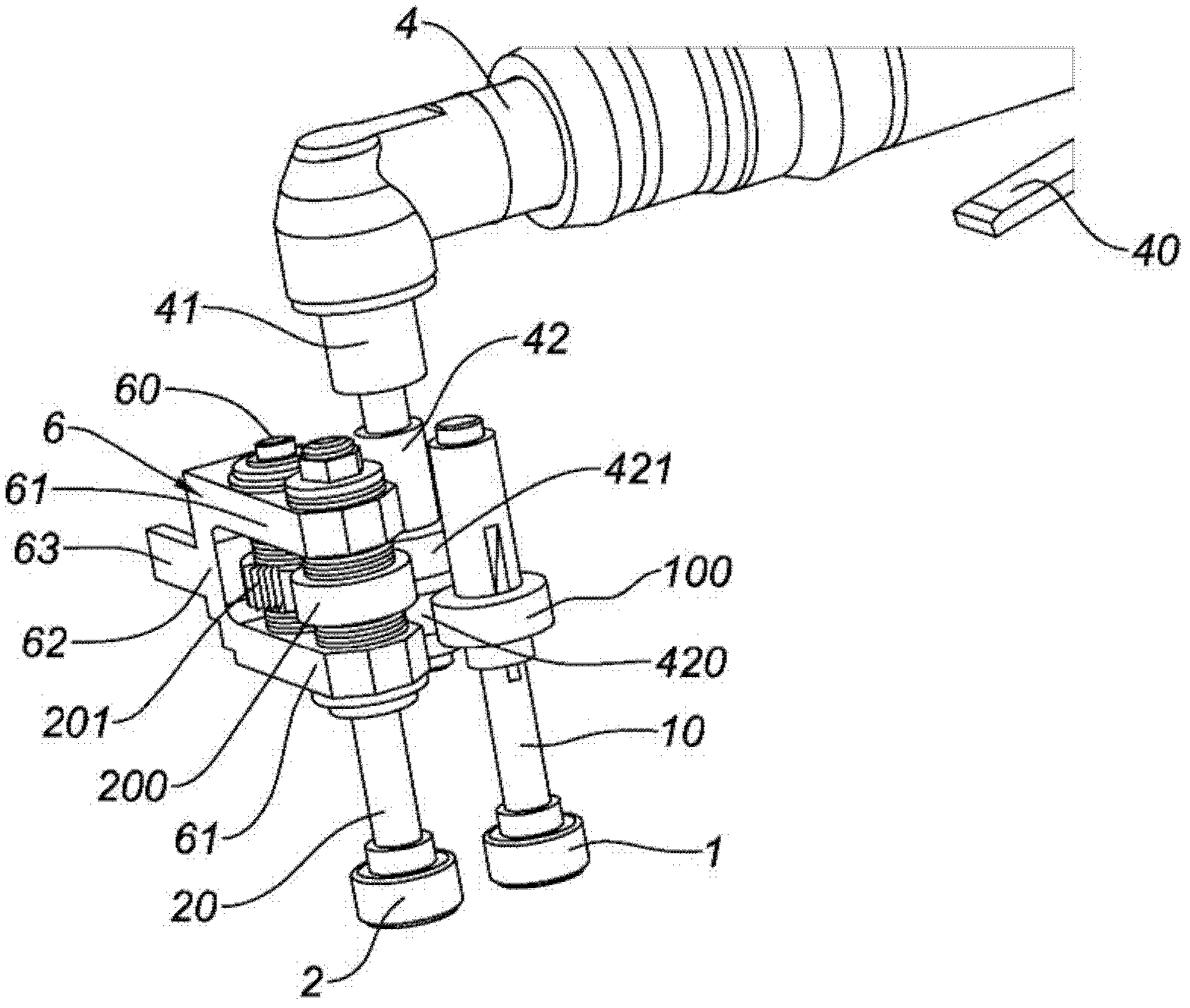
[0041] Figures 1 to 5 The illustrated tool comprises a first roller 1 and a second roller 2 , rotatably mounted and fastened respectively on first and second substantially parallel axes 10 and 20 .

[0042] The tool has a substantially parallelepiped-shaped tool body 3 . The body 3 comprises an upper surface 30 and a lower surface 31 connected to each other with four lateral surfaces 32 . Obtained from the perspective view, the lower surface 31 (the corresponding upper surface 30) and the two lateral surfaces 32 are in figure 1 in (correspondingly in figure 2 ) is visible.

[0043] The upper surface 30 is equipped with a fixed housing 300 of the pneumatic screwdriver 4 . Housing 300 is connected with screwdriver 4 in figure 2 more clearly visible in . Furthermore, the screwdriver 4 is provided with a lever 40 designed to control it.

[0044] The lower surface 31 is itself equipped with two mounted idler wheels 310 , arranged in a symmetrical manner on each side of th...


PUM


Abstract

The present invention relates to a tool for placing a joint in a leaf rebate of a vehicle, said tool comprising: first and second rollers (1, 2) that are rotatably mounted and secured onto substantially parallel first and second shafts (10, 20), respectively; a means (4) for rotating the first and second shafts; and a means for varying the distance between the first and second shafts, said variation means including a pivotal movement shaft that is substantially parallel to the second shaft, the variation means being arranged so as to pivot the second shaft around the pivotal movement shaft. Said tool is characterized in that it comprises a means (5) for actively controlling the variation means, said active control means being designed to adjust the distance between the first and second shaft.

Description

technical field [0001] The present invention relates to a tool for placing an engaging body in a door panel slot of a vehicle. Background technique [0002] The joints are placed on the notches of the door panels to ensure their tightness. Now, when the notch changes, the placement of the engagement body can prove to be problematic. [0003] In this respect, it is known from the prior art, in particular from document US 5,864,933, to use a tool comprising first and second rollers intended to press the engagement body against said notches, said first and second rollers Mounted on substantially parallel first and second shafts, respectively, the first and second shafts move relative to each other away from and towards each other as a function of the thickness of the slot. To do so, the second shaft is pivotally mounted on the passive structure about a pivot axis parallel to the second shaft. In this way, when the second shaft pivots about the pivot axis, the second shaft is...

Claims


Application Information

Patent Timeline
Patent Type & Authority Applications(China)
IPC IPC(8): B23P19/04B25B27/00B60J10/00
CPCB23P19/047B60J10/0088B60J10/45
Inventor P·阿尔瓦A·当德烈亚马泰奥
Owner PEZHO SITROEN AUTOMOBILS SA
Learn More