Vehicle body rear structure

A technology for the rear part and structure of the car body, which is applied in the field of improvement of the rear part structure of the car body, and can solve problems such as increasing the number of parts and increasing the weight of rigid parts

Inactive Publication Date: 2012-07-11
HONDA MOTOR CO LTD
View PDF6 Cites 12 Cited by
  • Summary
  • Abstract
  • Description
  • Claims
  • Application Information

AI Technical Summary

Problems solved by technology

As a result, the weight of the rigid parts (reinforcement, patch, etc.) fo

Method used


Image

  • Vehicle body rear structure
  • Vehicle body rear structure
  • Vehicle body rear structure

Examples


Embodiment

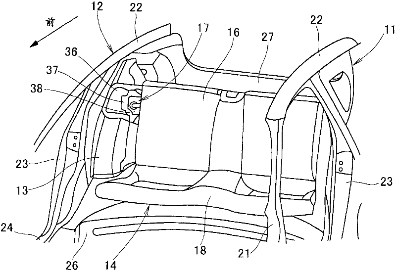
[0031] Such as figure 1 As shown, a rear wheelhouse inner panel 13 (only one reference numeral 13 is shown) is provided at each rear portion of a left vehicle body 11 and a right side vehicle body 12 constituting the vehicle body. The rear seat 14 is composed of a foldable seat back 16 and a seat cushion 18 . The seat back 16 is swingably attached to the rear end of the seat cushion 18 . Each rear wheelhouse inner panel 13 and the seat back 16 are detachably engaged via an engaging device 17 .

[0032] Left and right roof side rails 22 extend rearward from upper ends of left and right front pillars 21 (only one of which is shown in the figure). The left and right center pillars 23 extend downward from the middle portions of the left and right roof side rails 22 in the vehicle front-rear direction. The left and right side sills 24 (only one is shown in the figure) support the lower end of the center pillar 23 . The mid-floor cross member 26 connects the left and right side ...


PUM


Abstract

Disclosed is a vehicle body rear structure in which a rear wheelhouse inner panel (13) is provided with a seat striker (38) which disengages from an engagement part (16a) of a folding seat back (16). The rear wheelhouse inner panel (13) includes a wheelhouse extending part (13B) which extends integrally upward from the upper end of a wheelhouse base (13A). A stiffener (36) is attached to the wheelhouse extending part (13B). The wheelhouse extending part (13B) and the stiffener (36) form a dogleg-shaped closed section. The seat striker (38) is attached to a bracket (37) provided on the stiffener (36).

Description

technical field [0001] The present invention relates to an improvement in the rear structure of a vehicle body of a vehicle having a reclining seat back. Background technique [0002] As disclosed in Patent Document 1, there is known a vehicle body rear structure in which a reclining seat back of a rear seat is engaged with a suspension bell side of a vehicle body side. [0003] According to the vehicle body rear structure disclosed in Patent Document 1, a latch plate is provided on the rear seat back, a suspension bell is provided on the rear wheel house inner member on the vehicle body side, and the upper end of the suspension bell is A strike eye is mounted via a mounting plate into which the strike plate engages. [0004] Patent Document 1: Japanese Patent Application Laid-Open No. 11-115597 [0005] When the engagement position of the latch plate and the striker is close to the suspension bell, the load acting on the rear seat back can be supported by attaching the st...

Claims


Application Information

Patent Timeline
IPC IPC(8): B62D25/08
CPCB60N2/366B62D25/087
Inventor 星野重雄柱山直树
Owner HONDA MOTOR CO LTD
Why Eureka
Try Eureka