Hybrid reflectometer system (HRS)

A technology of reflectometer and measurement system, which is applied in the field of RF signal test and measurement system, can solve problems such as the difficulty of wheeler cap measurement, and achieve the effect of eliminating adverse RF effects

Inactive Publication Date: 2012-07-11
THE SEC OF STATE FOR DEFENCE IN HER BRITANNIC MAJESTYS GOVERNMENT OF THE UK OF GREAT BRITAIN & NORTHERN IRELAND
View PDF6 Cites 5 Cited by
  • Summary
  • Abstract
  • Description
  • Claims
  • Application Information

AI Technical Summary

Problems solved by technology

Previously, wheeler hat measurements were difficult due to the presence of RF interference at the input and output of the measurement system

Method used


Image

  • Hybrid reflectometer system (HRS)
  • Hybrid reflectometer system (HRS)
  • Hybrid reflectometer system (HRS)

Examples


Embodiment Construction

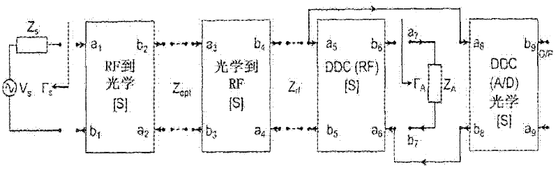
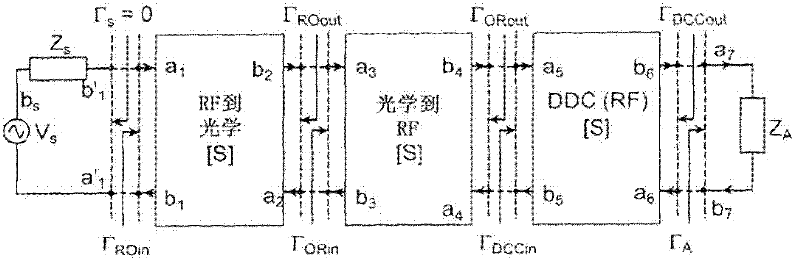
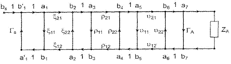
[0053] figure 1 Signal flow network analysis of HRS is shown, which can be used to reduce complex networks to relatively simple input-output relationships. The RF network can then be characterized using the scattering parameters. This technique is used to analyze the HRS and obtain the scattering parameters of the system. For network analysis, HRS consists of 4 modules; each module is a two-port network represented by a block with two input ports and two output ports. The ports associated with each module are:

[0054] RF to Optical Module

[0055] a1 input incident signal node

[0056] a2 output reflection signal node

[0057] b1 input reflected signal node

[0058] b2 output incident signal node

[0059] Optical to RF Module

[0060] a3 input incident signal node

[0061] a4 output reflected signal node

[0062] b3 input reflected signal node

[0063] b4 output incident signal node

[0064] Bidirectional Coupler RF (DDC(RF)) Module

[0065] a5 input incide...


PUM


Abstract

A RF signal test and measurement system capable of measuring forward and reverse signal parameters of RF components including Electrically Small Antennas (ESA) and capable of being integrated within a communications system to aid the automatic retuning of antennas.

Description

technical field [0001] The present invention relates to RF signal test and measurement systems capable of measuring forward signal parameters and reverse signal parameters of radio frequency (RF) components including antennas and in particular electrically small antennas (ESAs), and more particularly to RF signal test and measurement systems capable of being integrated in RF test and measurement system with automatic retuning of auxiliary antennas in communication systems. Background technique [0002] When developing RF devices, it is necessary to test RF components, such as antennas, independently or within an integrated system to verify their actual performance. Measuring antenna performance is usually accomplished by connecting the antenna to a reflectometer. This allows one to measure the antenna's scattering parameter (S-parameter) magnitude using a network analyzer, but calibration to account for unpredictable losses from radiating devices is problematic. This is es...

Claims


Application Information

Patent Timeline
Patent Type & Authority Applications(China)
IPC IPC(8): H04B17/00G01R29/10
CPCH04B17/004H04B17/0035H04B17/103H04B17/14H04B17/20G01R27/06G01R29/0871G01R29/10G01R31/2822H04B17/00G01R23/02
Inventor N·克劳S·J·珀金斯I·L·莫罗
Owner THE SEC OF STATE FOR DEFENCE IN HER BRITANNIC MAJESTYS GOVERNMENT OF THE UK OF GREAT BRITAIN & NORTHERN IRELAND
Why Eureka
Try Eureka