Intermittent coating apparatus

A coating device and coating technology are applied in the direction of devices and coatings for coating liquid on the surface, which can solve the problems of influence of coating thickness, difficulty in coating liquid coating, and difficulty in improving productivity.

Inactive Publication Date: 2012-07-18
FUJI KIKAI IND
View PDF6 Cites 21 Cited by
  • Summary
  • Abstract
  • Description
  • Claims
  • Application Information

AI Technical Summary

Problems solved by technology

Therefore, there is a problem that if the conveying speed of the above-mentioned substrate is not controlled below a certain value, it will be difficult to apply the coating liquid to the desired part of the substrate accurately, and it will be difficult to improve productivity.
In addition, the distance between the coating nozzle and the surface t

Method used


Image

  • Intermittent coating apparatus
  • Intermittent coating apparatus
  • Intermittent coating apparatus

Examples


Embodiment Construction

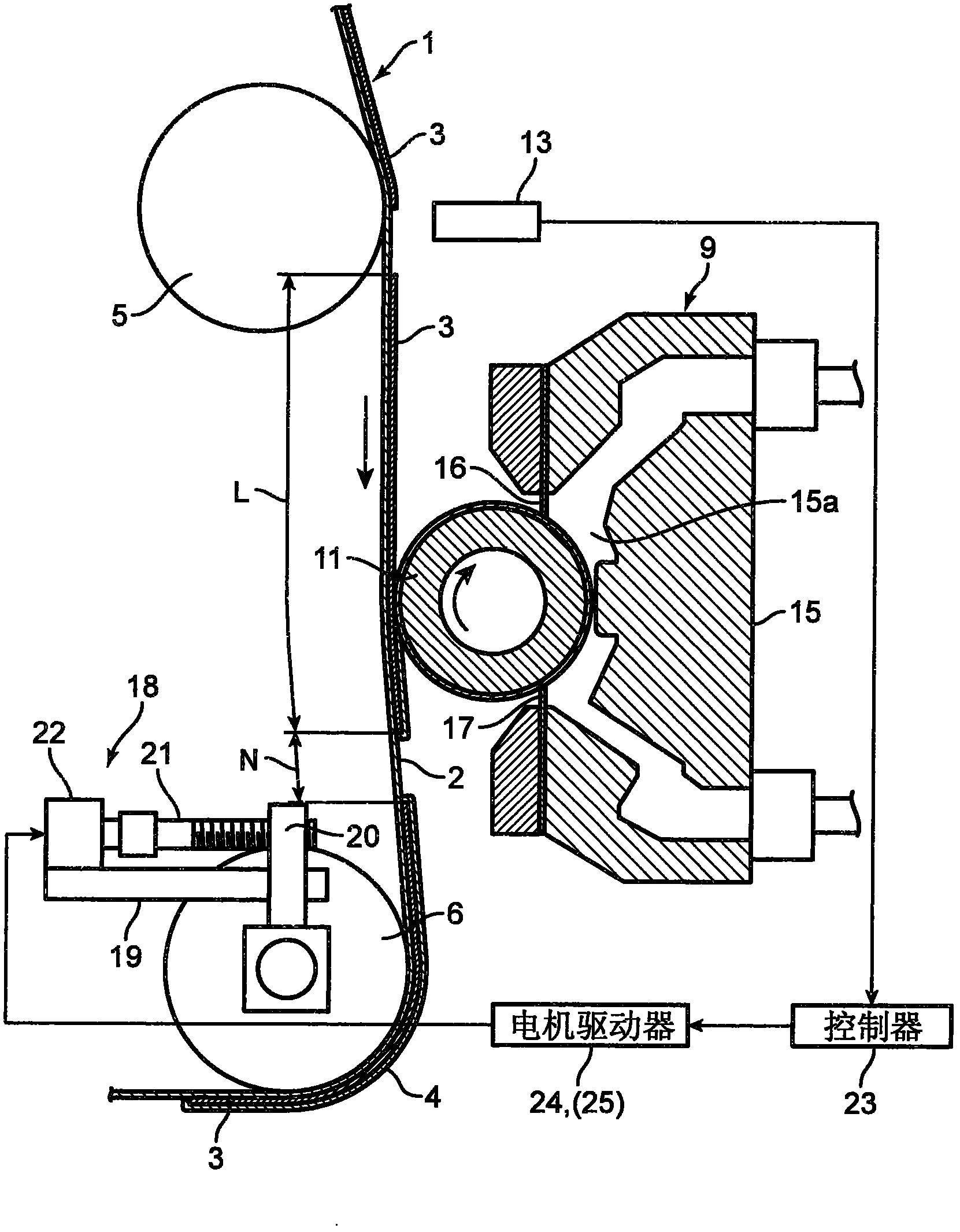
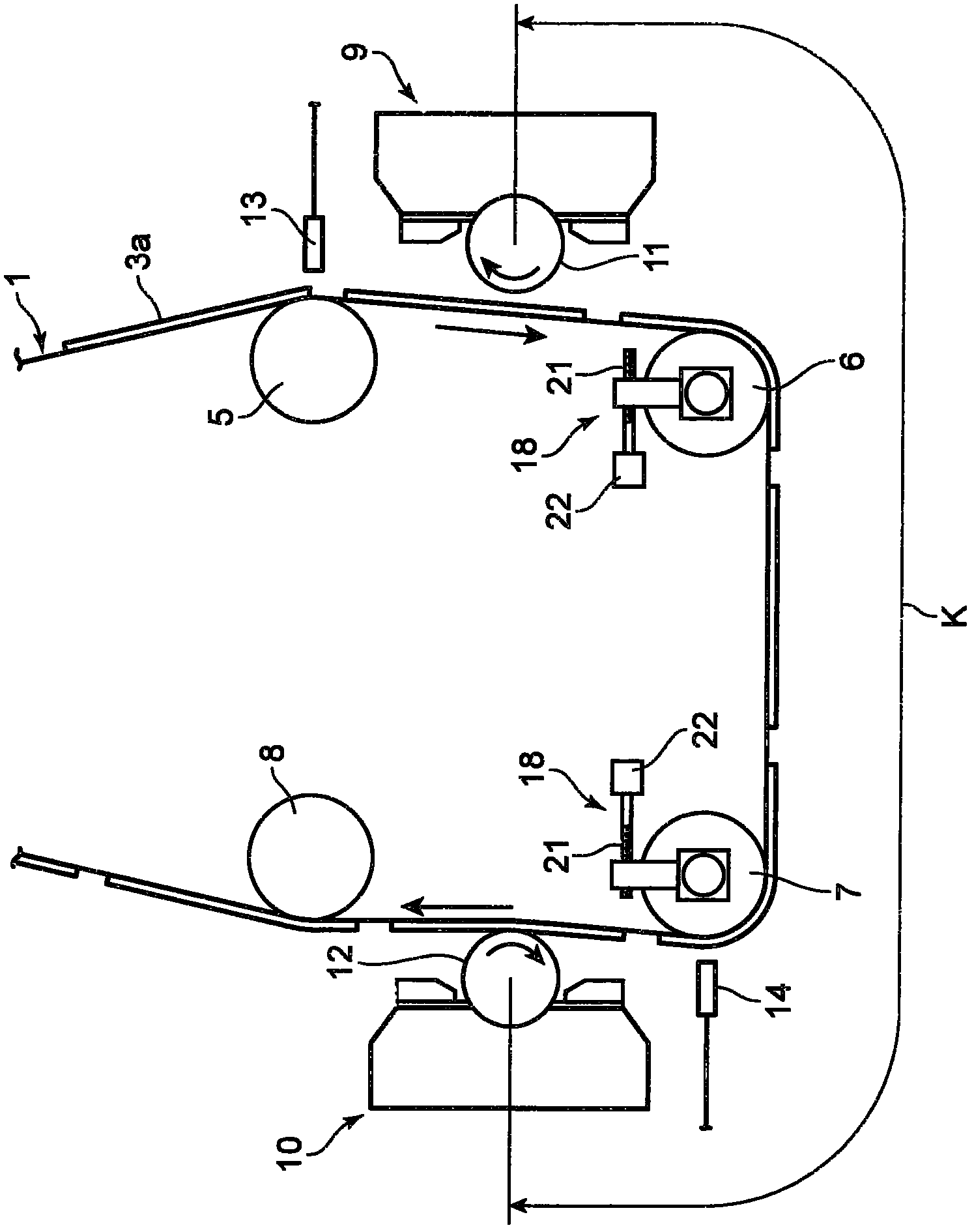
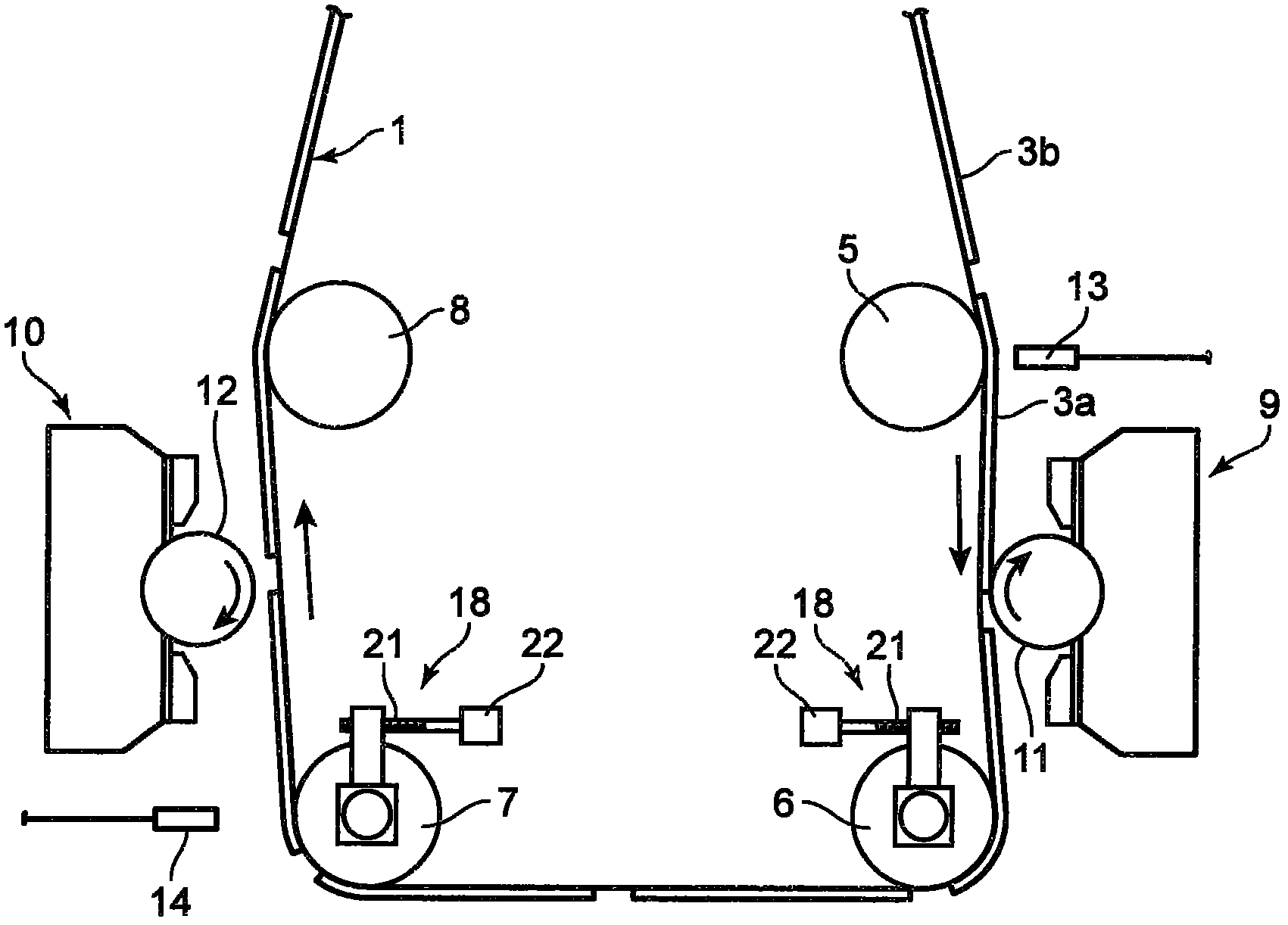
[0043] figure 1 as well as figure 2 The first embodiment of the intermittent coating device according to the present invention is shown in , which is a device for intermittently coating a coating agent on a substrate 1 constituting a negative electrode plate of a battery such as a lithium ion secondary battery. . Specifically, the intermittent coating device continuously arranges battery-use coatings 2 having a thickness of about 80 μm at predetermined intervals on a sheet-shaped current collector 2 composed of a copper sheet having a thickness of approximately 10 μm at a predetermined speed. When the substrate 1 made of the active material layer 3 is conveyed, a coating agent consisting of a ceramic paste is intermittently applied to the surface of the substrate 1 and dried to form a film having a film thickness of 10 μm or less, for example, The thin porous protective film 4 covering the surface of the battery active material layer 3 has a thickness of 2 μm±1 μm.

[0044...


PUM


Abstract

The invention provides an intermittent coating apparatus, wherein a substrate (1) to be conveyed in a conveying path is intermittently contacts coating rollers (11, 12). The intermittent coating apparatus comprises guide rollers (6, 7) arranged close to a plurality of coating rollers (11, 12) along the conveying path of the substrate (1) for limiting the movement direction of the substrate (1); a driving mechanism (18) for individually driving each of the guide rollers (6, 7). Therefore, the substrate (1) contacts or gets away from the coating rollers (11, 12), so that the coating agent is uniformly and respectively coated onto different regions of the substrate (1).

Description

technical field [0001] The present invention relates to an intermittent coating device for intermittently applying a coating agent to a substrate conveyed along a conveyance path by intermittently contacting the substrate with a coating roller. Background technique [0002] As shown in Japanese Patent Laid-Open Publication No. 2009-90274 (Patent Document 1), in the conventional intermittent coating method for intermittently coating a coating liquid on a continuously conveyed belt-shaped support (base material), The mechanism causes the lower surface of the above-mentioned support body to come into contact with the peripheral surface of the cylinder (coating roller) for coating with the above-mentioned coating liquid from the coating liquid accumulation part based on the rotation, so that the lower surface of the above-mentioned support body A coated portion coated with the coating liquid and a non-coated portion not coated with the coating liquid are formed on the surface. ...

Claims


Application Information

Patent Timeline
IPC IPC(8): B05C1/08B05C11/10B05C13/00H01M4/04H01M4/139
CPCY02E60/122Y02E60/10
Inventor 森川亮三浦秀宣中岛裕之安田芳章矶崎彻
Owner FUJI KIKAI IND
Why Eureka
Try Eureka