
A strip splicing one-way cloth oven

A technology of unidirectional cloth and oven, which is applied in the direction of drying, drying machine, drying gas arrangement, etc., can solve the problems of gaps or overlapping of strip unidirectional cloth, avoid gaps or overlapping, avoid offset, and increase ventilation sexual effect

Active Publication Date: 2022-07-08
ZHENGZHOU ZHONGYUAN DEFENSE MATERIAL
View PDF4 Cites 0 Cited by
  • Summary
  • Abstract
  • Description
  • Claims
  • Application Information

AI Technical Summary

Problems solved by technology

[0012] In order to solve the problems mentioned above, the present invention provides a strip splicing unidirectional cloth oven, which can avoid the gap or overlap of the unidirectional cloth caused by the offset of the strip during the transmission process.

Method used


Image

  • A strip splicing one-way cloth oven
  • A strip splicing one-way cloth oven
  • A strip splicing one-way cloth oven

Examples


Embodiment 1

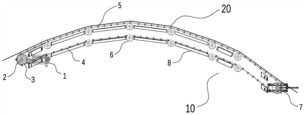
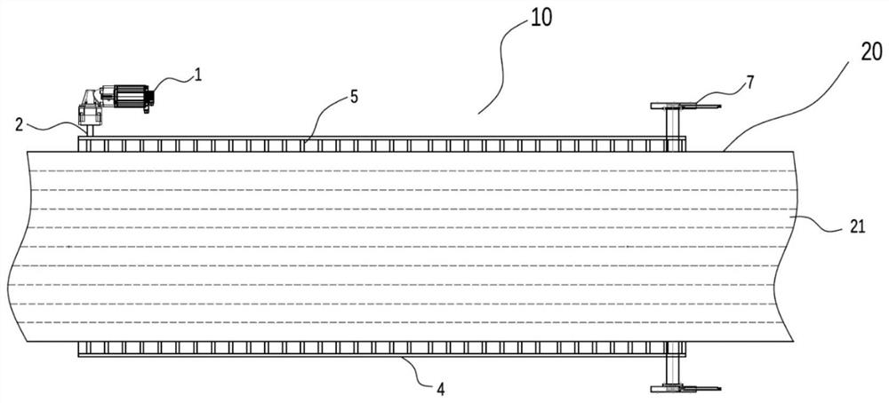
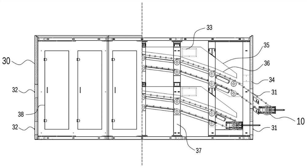
[0073] This embodiment relates to an oven for splicing unidirectional cloth with strips. like Figure 1-4 shown, image 3 , Figure 4 is a schematic structural diagram of the oven described in this embodiment, figure 1 , figure 2 It is a schematic diagram of the transmission device in the oven of this embodiment.

[0074] The oven for splicing unidirectional cloth with strips in this embodiment includes an oven body 30 and a gas circulation device 40 , the transmission device 10 is arranged in the box body 30 , and the transmission rod 5 of the transmission device 10 is made of carbon fiber composite material , the maximum deformation of the transmission rod 5 in the transmission process perpendicular to the axial direction of the transmission rod is less than 1 mm. Due to the small thermal expansion coefficient, low density and high rigidity of carbon fiber, it is not easy to deform in the synchronous transmission of wide-format materials such as unidirectional cloth 20...

Embodiment 2

[0082] This embodiment is a further description of the structure of the transmission device 10 in the oven of the embodiment 1 on the basis of the embodiment 1.

[0083] like figure 1 and figure 2 As shown, the transmission device 10 includes: a drive motor 1, the drive motor 1 is connected to a drive shaft 2, the drive shaft 2 is provided with two drive sprockets 3, and the distance between the two drive sprockets 3 is greater than the distance between the two drive sprockets 3 The width of the one-way cloth 20 conveyed by the device, the outer circular surface of the driving sprocket 3 is provided with meshing teeth, the transmission device 10 is provided with a transmission chain 4, there are two transmission chains 4, and the two transmission chains 4 are arranged at intervals. A plurality of transmission rods 5 are respectively fixed at both ends of the transmission rods 5 on two transmission chains 4 , and the two transmission chains 4 are respectively engaged with the...


PUM


Abstract

The present invention relates to an oven for splicing unidirectional cloth with strips, including a transmission device 10, a box body 30, and a gas circulation device 40. It is characterized in that the transmission device 10 is supported by the transmission rods 5 arranged at intervals to support the unidirectional cloth 20 to advance, wherein The maximum deformation of the transmission rod 5 in the direction perpendicular to the transmission rod during the transmission process is less than 10mm. The transmission device 10 and the one-way cloth 20 are driven by different power sources respectively. The stepping speed of the transmission device 10 and the transmission of the one-way cloth 20 The speed is the same, the travel route of the transmission rod 5 is an arc that is arched in the direction of the one-way distribution 2, and the box body 30 is provided with a gas distribution device 35, and the air outlet side section 36 of the gas distribution device The travel path shape of the transmission rod 5 is the same. The transmission device 10 provided by the present invention only supports the one-way cloth 20 during the transmission process, and the supporting force for each strip 21 in the one-way cloth 20 is uniform, which can avoid the deviation caused by the different tension of the strips 21. The unidirectional cloth 20 has defects such as gaps or overlaps.

Description

technical field [0001] The invention relates to an oven for splicing unidirectional cloth with strips, in particular to an oven comprising a transmission device for splicing unidirectional cloth with strips. Background technique [0002] Unidirectional fabric, refers to a large amount of textile yarn or roving in one direction (usually warp, but also weft unidirectional fabric), and no yarn in the other direction, or only a small amount and usually fine yarn, cloth A textile with all strength in one direction. [0003] There are three main types: [0004] 1. Woven unidirectional cloth, generally warp unidirectional cloth, is mainly used for seismic repair and reinforcement of building bridges, such as unidirectional carbon fiber cloth. [0005] 2. Stitched unidirectional fabric, special equipment arranges fiber yarns in one direction, and stitched fabrics made of polyester yarns are mainly used in aerospace industry and shipbuilding industry, and also used for building rei...

Claims


Application Information

Patent Timeline
Patent Type & Authority Patents(China)
IPC IPC(8): B05D3/04F26B13/12F26B21/00F26B21/06F26B25/02
CPCB05D3/0413F26B13/12F26B21/001F26B21/004F26B21/06F26B25/02
Inventor 张键明姬长干朱坤艳张亚飞满长阵史睢宁李东亮赵鹏时志鹏
Owner ZHENGZHOU ZHONGYUAN DEFENSE MATERIAL
Learn More