Unloading device for energy-saving lamp spiral tubes

A technology of unloading device and spiral tube, which is applied in the field of energy-saving lamp spiral tube processing device, can solve the problems of waste of human resources, high labor intensity, high processing cost, etc., and achieve the effect of reducing labor intensity and saving manufacturing cost

Inactive Publication Date: 2012-07-18
晋中开发区锋奇赫机械有限公司
View PDF2 Cites 0 Cited by
  • Summary
  • Abstract
  • Description
  • Claims
  • Application Information

AI Technical Summary

Problems solved by technology

[0002] At present, on the equipment that completes the bending of the glass spiral tube of energy-saving lamps, the clamping device used to clamp the glass spiral tube of energy-saving lamps is realized. The unloading process of the glass spiral tube bending equipment of energy-saving lamps is manually It is completed by opening the clamp device, which not only causes a waste of human resources, but also has high labor intensity and low efficiency for workers, and also brings high processing costs.

Method used


Image

  • Unloading device for energy-saving lamp spiral tubes
  • Unloading device for energy-saving lamp spiral tubes
  • Unloading device for energy-saving lamp spiral tubes

Examples


Embodiment Construction

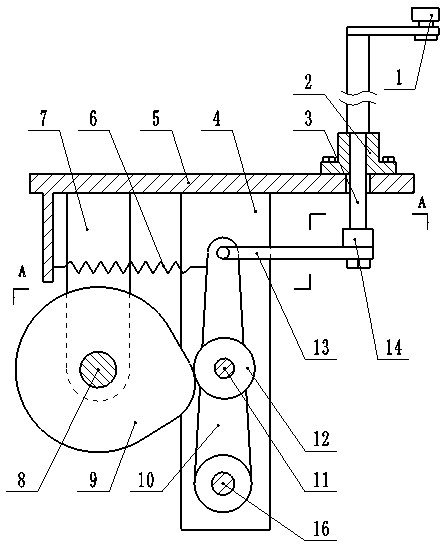
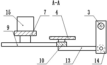
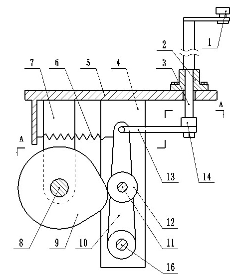
[0011] Such as figure 1 , figure 2 As shown, the unloading device for the spiral tube of the energy-saving lamp of the present invention includes: a rotating shaft 3, a first support 4, a frame 5, a cam 9, a swing arm 10, and a connecting rod 13, which are arranged at the lower part of the frame 5 horizontally The first support 4 and the second support 7 are fixed, the motor 15 is mounted on the second support 7, the cam 9 is mounted on the output shaft 8 of the motor 15; the swing arm 10 is mounted on the first support 4 through the shaft 16 On the upper part of the swing arm 10, a first roller 12 is fixed through the shaft 11, the outer dome of the first roller 12 is on the cam 9, and the upper part of the swing arm 10 is fixed with a tension spring 6. The other end of the tension spring 6 It is fixed at the lower part of the frame 5; the upper part of the swing arm 10 is connected to one end of the connecting rod 13, and the other end of the connecting rod 13 is connected t...


PUM


Abstract

The invention relates to an unloading device for energy-saving lamp spiral tubes, belonging to the technical field of processing units of energy-saving lamp spiral tubes. The invention aims to provide an unloading device for opening an energy-saving lamp spiral tube gripping mechanism, which can lower the labor intensity of the workers, enhance the work efficiency and save the processing cost. The technical scheme is as follows: the lower part of a horizontally arranged frame is fixed with a first bracket and a second bracket, a motor is installed on the second bracket, and a cam is installed on an output shaft of the motor; a swing arm is installed on the first bracket through a shaft, the middle part of the swing arm is fixed with a first roller through a shaft, the outer circle of the first roller abuts against the cam, the upper part of the swing arm is fixed with a tension spring, and the other end of the tension spring is fixed to the lower part of the frame; and the upper part of the swing arm is connected with one end of a connecting rod, the other end of the connecting rod is connected with a rotating shaft through a mounting plate, and the rotating shaft is installed on the frame through a rotating shaft seat. The invention is used for processing energy-saving lamp spiral tubes.

Description

Technical field [0001] The discharge device of the spiral tube of the energy-saving lamp of the present invention belongs to the technical field of the spiral tube processing device of the energy-saving lamp. Background technique [0002] At present, on the equipment that completes the bending of the glass spiral tube of the energy-saving lamp, the clamping device is used to clamp the glass spiral tube of the energy-saving lamp. The unloading process of the glass spiral tube bending device of the energy-saving lamp is done manually. The clamping device is opened to complete, which not only causes a waste of human resources, but also causes high labor intensity and low efficiency of the workers, as well as high processing costs. Summary of the invention [0003] The technical problem to be solved by the present invention is to provide an unloading device that can reduce the labor intensity of workers, improve work efficiency, and save processing costs. [0004] In order to solve the...

Claims


Application Information

Patent Timeline
Patent Type & Authority Applications(China)
IPC IPC(8): C03B23/045C03B23/06
Inventor 胡振强
Owner 晋中开发区锋奇赫机械有限公司
Why Eureka
Try Eureka