
Ventilating cap

A ventilation cap and cap body technology, applied in the field of ventilation caps, can solve problems such as blockage of dust filters and damage to ventilation caps.

Inactive Publication Date: 2012-07-18
WORLD TRANSMISSION TECH TIANJIN SHARE LTD
View PDF6 Cites 2 Cited by
  • Summary
  • Abstract
  • Description
  • Claims
  • Application Information

AI Technical Summary

Problems solved by technology

[0004] Especially in the special working conditions of underground coal mines, due to the presence of more particles and dust, it is easy to cause the blockage of the dust-proof net in the vent cap
When coal hits the reducer when going underground, it is easy to cause damage to the vent cap

Method used


Image

  • Ventilating cap
  • Ventilating cap

Examples


Embodiment Construction

[0016] The following will clearly and completely describe the technical solutions in the embodiments of the present invention with reference to the accompanying drawings in the embodiments of the present invention. Obviously, the described embodiments are only some of the embodiments of the present invention, not all of them. Based on the embodiments of the present invention, all other embodiments obtained by persons of ordinary skill in the art without making creative efforts belong to the protection scope of the present invention.

[0017] The invention discloses a vent cap to prolong the service life of the vent cap.

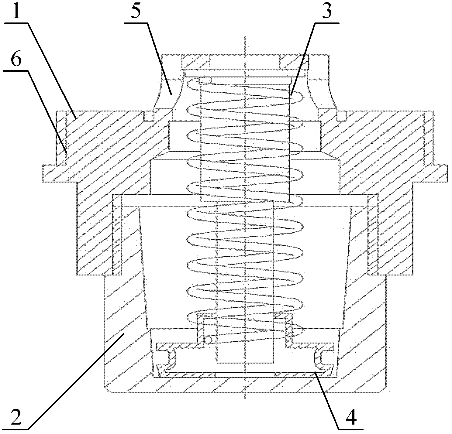
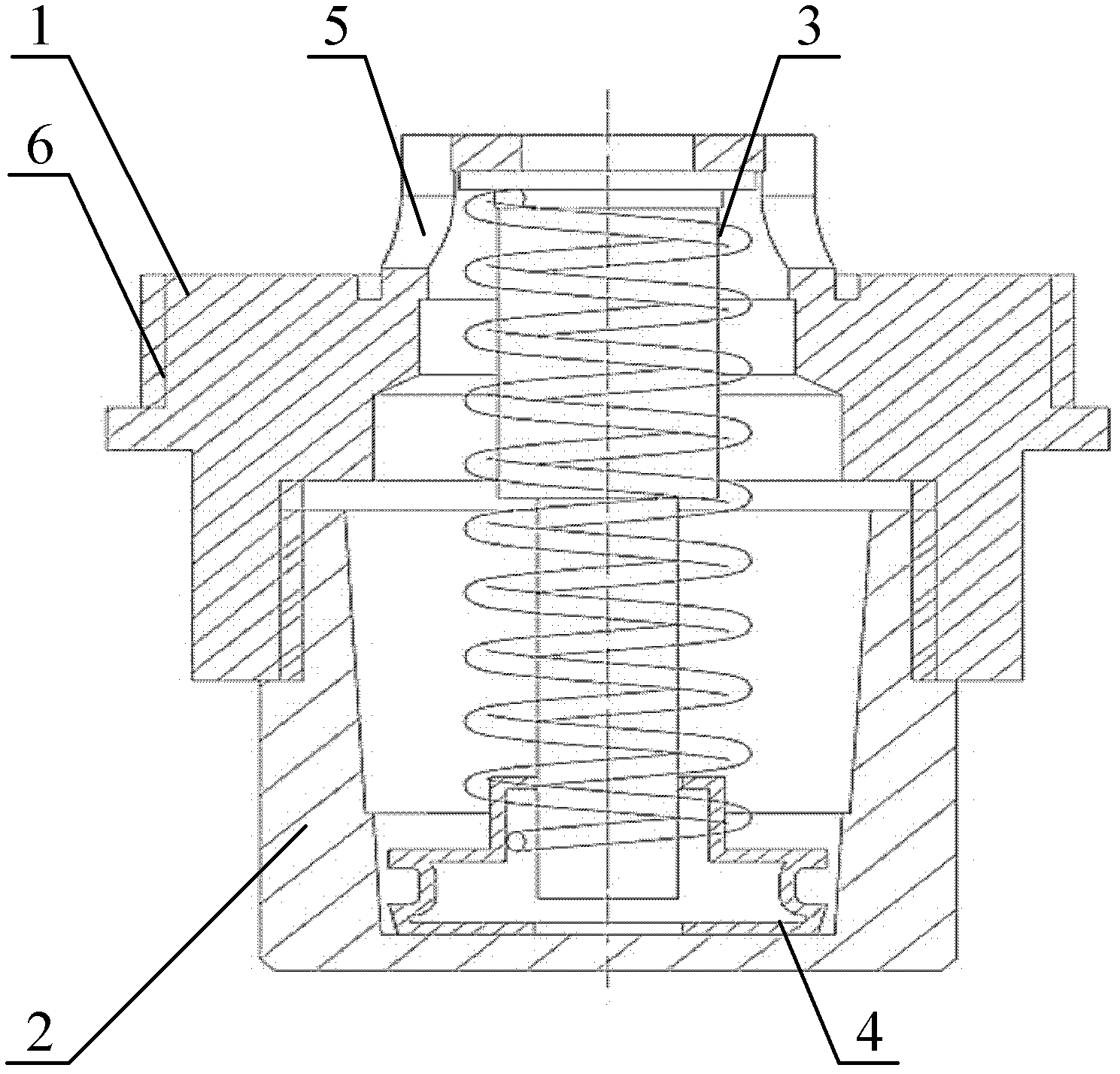
[0018] Such as figure 1 As shown, the vent cap includes a cap body 1, and a plug 2 arranged on the cap body 1, the plug 2 and the inside of the cap body 1 form a cavity, and the cap body 1 is provided with a communication cavity and a reducer The air inlet 5 of the cap body 1 and the plug 2 are provided with a gap for transporting the gas to the outside on t...


PUM


Abstract

The embodiment of the invention discloses a ventilating cap which comprises a cap body, and a plug arranged on the cap body, wherein cavities are formed inside the plug and the cap body, the cap body is provided with a gas inlet for communicating the cavity with a speed reducer, and a gap for conveying gas to outside is arranged on a surface where the cap body and the plug are matched. When the ventilating cap is used, the cap body is directly arranged on the speed reducer, compared with the traditional ventilating cap of the speed reducer, the ventilating cap does not have a filter net, and is in a pure mechanical inside structure. When the speed reducer continuously operates to enable the temperature increases, expanded gas enters the ventilating cap through the gas inlet on the cap body and is discharged outside the speed reducer through the gap between the cap body and the plug, thus the ventilating effect is achieved.

Description

technical field [0001] The invention relates to the technical field of mechanical accessories, and more specifically, relates to a vent cap. Background technique [0002] The vent cap is mainly used as a portal for gas exchange between machinery and the outside world, and is suitable for most machines such as reducers and engines that need to exchange gas with the outside world. For example: the vent cap of the reducer is mainly used to balance the atmospheric pressure inside and outside the reducer to achieve internal and external gas exchange. [0003] When the reducer is in continuous operation, the temperature will become very high, and the gas inside the reducer will expand. In order not to damage the dynamic oil seal of the reducer, it is necessary to install a breather cap on the reducer to play a role in ventilation. Under the working conditions of coal mines, there are many particles and dust, and coal lumps often hit the reducer. And the vent cap used in the exis...

Claims


Application Information

Patent Timeline
Patent Type & Authority Applications(China)
IPC IPC(8): F16H57/027F02B77/00
Inventor 胡炜
Owner WORLD TRANSMISSION TECH TIANJIN SHARE LTD
Learn More