
A heat exchanger with microchannels or/and thin channels on two or more sides

A thin-channel and micro-channel technology, applied in heat exchanger types, indirect heat exchangers, lighting and heating equipment, etc., can solve problems such as energy waste, increase fan output power, and short wind-side flow, and achieve optimal field Effects of synergistic effect, improvement of heat transfer coefficient, and improvement of temperature efficiency

Active Publication Date: 2016-01-20
吴江科技创业园管理服务有限公司
View PDF6 Cites 0 Cited by
  • Summary
  • Abstract
  • Description
  • Claims
  • Application Information

AI Technical Summary

Problems solved by technology

[0002] Although the existing micro-channel heat sink has a good heat dissipation effect, due to the limitation of its structural form, there are still the following deficiencies: the flow of the micro-channel is too long, the flow resistance of the fluid increases, the flow of the wind side is too short, and the utilization effect of the wind Poor, the output power of the fan is increased correspondingly, resulting in energy waste; it is difficult to increase the flow rate, and it is difficult to form a large-scale heat exchange; the application range is limited, and heat exchange between liquid and liquid is not possible, only limited to gas and liquid or gas heat exchange with gas

Method used


Image

  • A heat exchanger with microchannels or/and thin channels on two or more sides
  • A heat exchanger with microchannels or/and thin channels on two or more sides
  • A heat exchanger with microchannels or/and thin channels on two or more sides

Examples


Embodiment 1

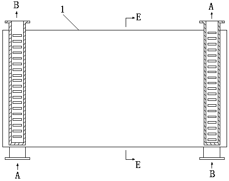
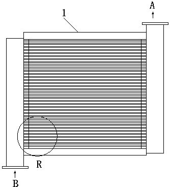
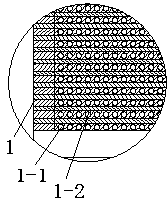
[0021] refer to Figure 1-3 , both sides of the present embodiment adopt the heat exchanger 1 of microchannel, comprise the microchannel 1-1 that is used for medium A to exchange heat and the microchannel 1-2 that is used for medium B to exchange heat, described heat exchanger 1 Adopt pure countercurrent heat exchange; the microchannels 1-1 for medium A for heat exchange and the microchannels 1-2 for medium B for heat exchange are both microchannels with a diameter of 0.5mm, and they are alternated in order Arranged in parallel, the inlet and outlet of the microchannel 1-1 for medium A to exchange heat and the microchannel 1-2 for medium B to exchange heat are respectively arranged on both sides of the channel in parallel arrangement, and the inlet passes through The horizontal distribution channel is connected with the corresponding channel, and the outlet is connected with the corresponding channel through the horizontal confluence channel. Of course, the microchannel may a...

Embodiment 2

[0024] refer to Figure 4-6 , the three sides of the present embodiment adopt the heat exchanger 2 of thin channel, and described heat exchanger 2 is provided with the circulation channel 2-1 that is used for medium A to exchange heat, and the circulation channel 2-1 that is used for medium B to exchange heat 2, there is also a circulation channel 2-3 for the medium C to exchange heat, which is characterized in that: the circulation channel 2-1 for the medium A to exchange heat, and the circulation channel for the medium B to exchange heat 2-2. The circulation channels 2-3 used for medium C to exchange heat all adopt thin channels with a diameter of 3 mm, and the rest are the same as in embodiment 1.

Embodiment 3

[0026] refer to Figure 7 , the two sides of the present embodiment adopt the heat exchanger 3 of microchannel, and the difference with embodiment 1 is: described microchannel inlet and outlet that is used for medium A to exchange heat does not have corresponding lateral distribution channel and confluence channel, and directly One end of the microchannel is connected with a channel cover I3-1, and the other end is connected with a fluid channel cover II3-2, which become the inlet and outlet.


PUM


Abstract

A heat exchanger adopting micro-channels or / and narrow channels on two sides or multiple sides comprises circulation channels for heat exchange of different media and adopts a pure countercurrent heat exchange mode. The circulation channels are the micro-channels or / and narrow channels and sequentially and alternately arranged in parallel, inlet and outlets of the circulation channels arranged at least one side are arranged on two sides of each of the parallel-arranged channels, the inlets are connected with corresponding channels through transverse distributary channels, and the outlets are connected with corresponding channels through transverse confluence channels. The heat exchanger adopting the micro-channels or / and narrow channels on two sides or multiple sides are good in heat exchange effect, capable of saving energy and wide in application range.

Description

technical field [0001] The invention relates to a heat exchanger, in particular to a heat exchanger with microchannels or / and thin channels on two or more sides. Background technique [0002] Although the existing micro-channel radiator has a good heat dissipation effect, due to the limitation of its structural form, there are still the following deficiencies: the flow of the micro-channel is too long, the flow resistance of the fluid increases, the flow of the wind side is too short, and the utilization effect of the wind Poor, the output power of the fan is increased accordingly, resulting in energy waste; it is difficult to increase the flow rate, and it is difficult to form a large-scale heat exchange; the application range is limited, and heat exchange between liquid and liquid is not possible, only limited to gas and liquid or gas Exchange heat with gas. [0003] Prior to this, Liu Xiaojiang applied for an invention "a pure countercurrent honeycomb plate-fin heat exch...

Claims


Application Information

Patent Timeline
Patent Type & Authority Patents(China)
IPC IPC(8): F28D9/00
Inventor 刘赟
Owner 吴江科技创业园管理服务有限公司
Learn More