
Three-dimensional topography central perturbation composite grating projection measuring method and device

A composite grating, three-dimensional topography technology, applied in measurement devices, optical devices, instruments, etc., can solve the problems of reduced accuracy, low efficiency, and affecting the speed of measurement.

Inactive Publication Date: 2012-07-18
TIANJIN UNIV
View PDF4 Cites 32 Cited by
  • Summary
  • Abstract
  • Description
  • Claims
  • Application Information

AI Technical Summary

Problems solved by technology

Fourier transform profilometry only needs one grating image to obtain the phase distribution. This method is suitable for dynamic measurement, but the accuracy is reduced due to the influence of spectral aliasing
Phase measurement profilometry has high measurement accuracy, but it needs to continuously project multiple images to the measured object, which affects the measurement speed
The traditional composite grating contains multiple phase-shifted grating images in one grating image, but the efficiency of obtaining the correct phase distribution from the phase-shifted grating is not high

Method used


Image

  • Three-dimensional topography central perturbation composite grating projection measuring method and device
  • Three-dimensional topography central perturbation composite grating projection measuring method and device
  • Three-dimensional topography central perturbation composite grating projection measuring method and device

Examples


Embodiment Construction

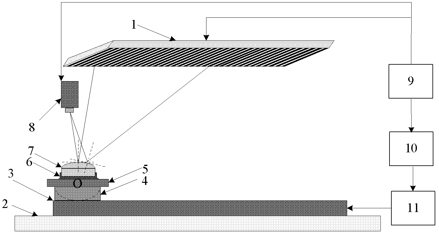
[0029] The technical scheme that the present invention takes is center perturbation composite grating projection method, and its realization method is as follows:

[0030] The expression for the traditional sinusoidal grating phase shift fringe projected by LCD is:

[0031] I n (x,y)=A+Bcos(2πy / t y +π(n-1) / 2) n=1, 2, Λ4 (1)

[0032] Among them, A, B, t y They are the background light intensity, contrast, and fringe period (in pixels), and (x, y) are the coordinates of the image coordinate system.

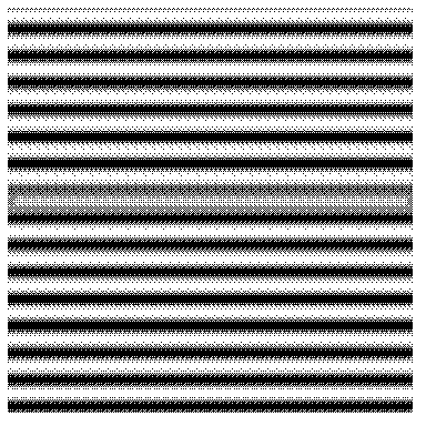
[0033] Change the brightness of the central stripes of the traditional sinusoidal grating (the fourth frame, that is, the n=4 sinusoidal grating), so that the central stripe contains coding information different from other stripes to form perturbation information. Assuming that the central fringe is the Qth fringe, the grating containing perturbation information is only different from the traditional grating at the Qth fringe. The expression of the grating with perturbation inf...


PUM


Abstract

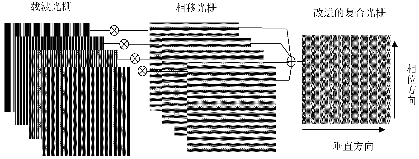
The invention relates to optical three-dimensional topography measurement and structured light technology. In order to improve resolution and interference resistance of a coded grating of the optical three-dimensional measurement and improve the speed without reducing the measurement precision, the invention provides a three-dimensional topography central perturbation composite grating projection measuring method, which is characterized in that: four carrier gratings of different frequencies are used for respectively modulating four frames of phase-shift sinusoidal gratings which are vertical to the carrier gratings, wherein the brightness of a central stripe of a fourth frame of phase-shift sinusoidal grating is changed to be superimposed into a central perturbation composite grating; a liquid crystal display (LCD) device is used for projecting the central perturbation composite grating onto a measured object to obtain a deformed grating which is modulated by a object profile; two-dimensional Fourier transformation is performed on the deformed grating to be filtered by an appropriate band-pass filter, then Fourier inverse transformation is carried out, and a module value is obtained; and finally, a superimposed phase is solved by an improved four-step phase-shift method, and the phase distribution which is modulated by the profile of the measured object is obtained by adding the perturbation information. The three-dimensional topography central perturbation composite grating projection measuring method and a device are mainly used for the optical measurement.

Description

technical field [0001] The invention relates to optical three-dimensional shape measurement and structured light technology. In the structured light method, in order to improve the reliability of grating projection measurement, it is necessary to encode the grating. The invention relates to a coding method and a measuring device used in three-dimensional shape measurement of specular reflection objects. Specifically, the invention relates to a method and device for measuring a three-dimensional shape center perturbation composite grating projection. Background technique [0002] Optical three-dimensional measurement technology has been widely used and developed in high-speed inspection, product development, quality control, reverse engineering, CAD / CAM and other fields due to its advantages of high precision, high efficiency and non-contact. However, in the existing mature technology, optical three-dimensional measurement is mainly aimed at diffuse reflection objects, and ...

Claims


Application Information

Patent Timeline
IPC IPC(8): G01B11/25
Inventor 季莉栓刘书桂张宏伟李绍辉韩淑建
Owner TIANJIN UNIV
Learn More