Optimized focal area for augmented reality displays

A technology of focusing area and display, applied in the field of optimizing focusing area

Active Publication Date: 2012-07-18
MICROSOFT TECH LICENSING LLC
View PDF15 Cites 53 Cited by
  • Summary
  • Abstract
  • Description
  • Claims
  • Application Information

AI Technical Summary

Problems solved by technology

In a display like this, display re...

Method used


Image

  • Optimized focal area for augmented reality displays
  • Optimized focal area for augmented reality displays
  • Optimized focal area for augmented reality displays

Examples


Embodiment Construction

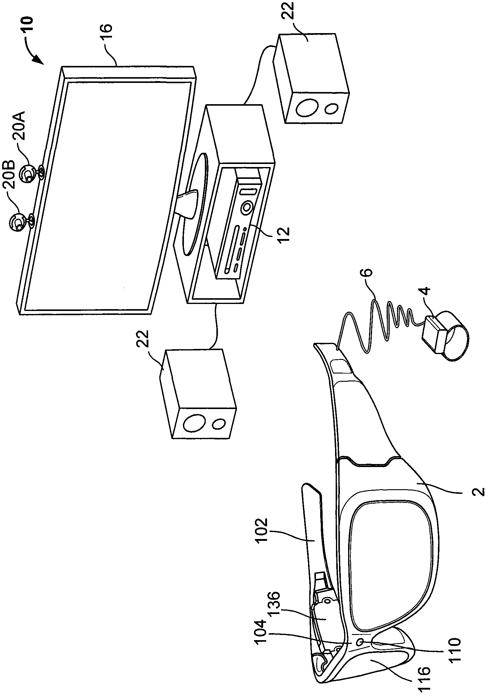
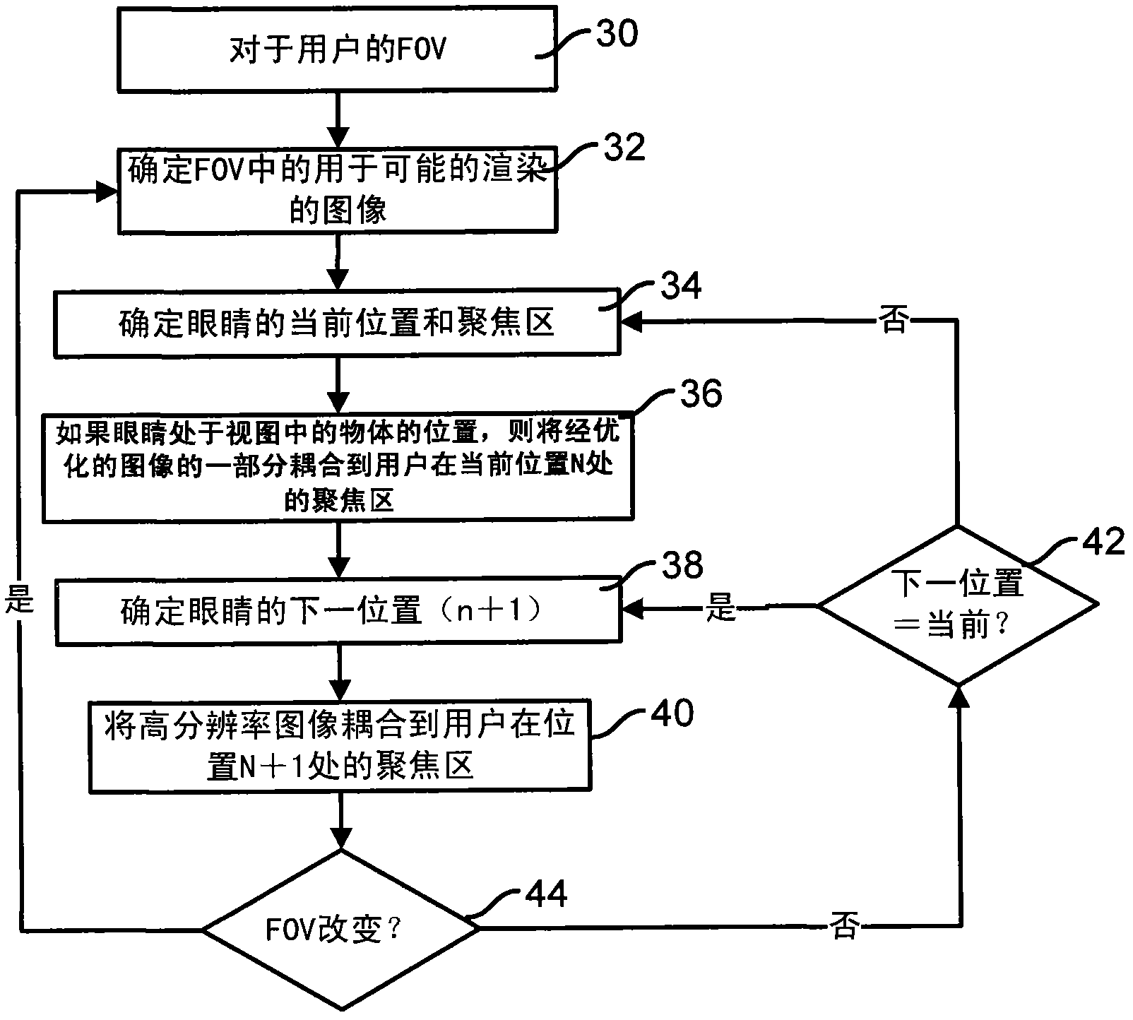
[0032] A technique for enhancing a user's experience when using a near-eye display device is disclosed. The user views the scene through a near-eye display device, such as a head-mounted display device. Determine the user's field of view as the environment or space the user is looking at. Renders an image optimized for use relative to the field of view. A user's focal zone is determined by tracking the position of the user's eyes within the field of view. Display of the optimized image is provided by coupling an optimized portion of the image to the user's focal region (in one case the user's fovea) to reduce the processing and energy required for the display. The user's eye position is tracked, and a next eye position is calculated to position the portion of the image at the next position based on the movement of the user's eye to the next position.

[0033] The positioning of the optimized portion of the image is performed by any number of different display devices, inclu...


PUM


Abstract

The invention relates to an optimized focal area for augmented reality displays, and provides a method and a system that enhances a user's experience when using a near eye display device, such as a see-through display device or a head mounted display device. An optimized image for display relative to a field of view of a user in a scene is created. The user's head and eye position and movement are tracked to determine a focal region for the user. A portion of the optimized image is coupled to the user's focal region in the current position of the eyes, a next position of the head and eyes predicted, and a portion of the optimized image coupled to the user's focal region in the next position.

Description

technical field [0001] The present invention relates to optimized focal regions for extended reality displays. Background technique [0002] Extended reality is a technology that allows virtual images to be blended with real-world physical environments or spaces. In general, near-eye displays use a combination of optics and stereo vision to focus virtual images into space. In a display like this, display resolution and processing are at a premium. [0003] In some cases, virtual images displayed to a user via a near-eye display device may include virtual images or objects containing highly detailed graphics. A user wearing a near-eye display device is typically presented with a large amount of information that the user may not necessarily be interested in viewing. Contents of the invention [0004] The outlined technique includes a method for presenting optimized images to a user. Creates an image optimized for display relative to the user's entire field of view in the...

Claims


Application Information

Patent Timeline
IPC IPC(8): G02B27/01
CPCG02B27/0093G06F3/013G02B27/017G02B2027/0178G02B2027/014G02B2027/0187G06F3/0304
Inventor A·巴-泽埃夫J·R·刘易斯G·克莱因
Owner MICROSOFT TECH LICENSING LLC
Why Eureka
Try Eureka