High lighting-effect low power-consumption light-emitting diode (LED) area light source initiative-passive light-emitting alarm device

A technology of LED surface light source and warning device, applied in display devices, signal devices, visible signal devices, etc., can solve the problems of LED influence, high power consumption, monotonous pattern or text, etc., and achieve low power consumption, high light efficiency, Good visibility

Inactive Publication Date: 2012-07-18
董飞鸿
View PDF8 Cites 13 Cited by
  • Summary
  • Abstract
  • Description
  • Claims
  • Application Information

AI Technical Summary

Problems solved by technology

This technology is largely affected by the size, structure, pattern or text complexity of the reflective signboard. When the signboard is large or the pattern and text are more complicated, a large number of LEDs are needed to outline the pattern or text. Not to mention fill patterns or text
Therefore, the patterns or characters displayed by this technology are generally monotonous and abstract, and there are also problems of high power consumption, black spots and black spots when individual LEDs are damaged, which will affect the integrity and visibility of the entire pattern or characters. question

Method used


Image

  • High lighting-effect low power-consumption light-emitting diode (LED) area light source initiative-passive light-emitting alarm device
  • High lighting-effect low power-consumption light-emitting diode (LED) area light source initiative-passive light-emitting alarm device
  • High lighting-effect low power-consumption light-emitting diode (LED) area light source initiative-passive light-emitting alarm device

Examples


Embodiment Construction

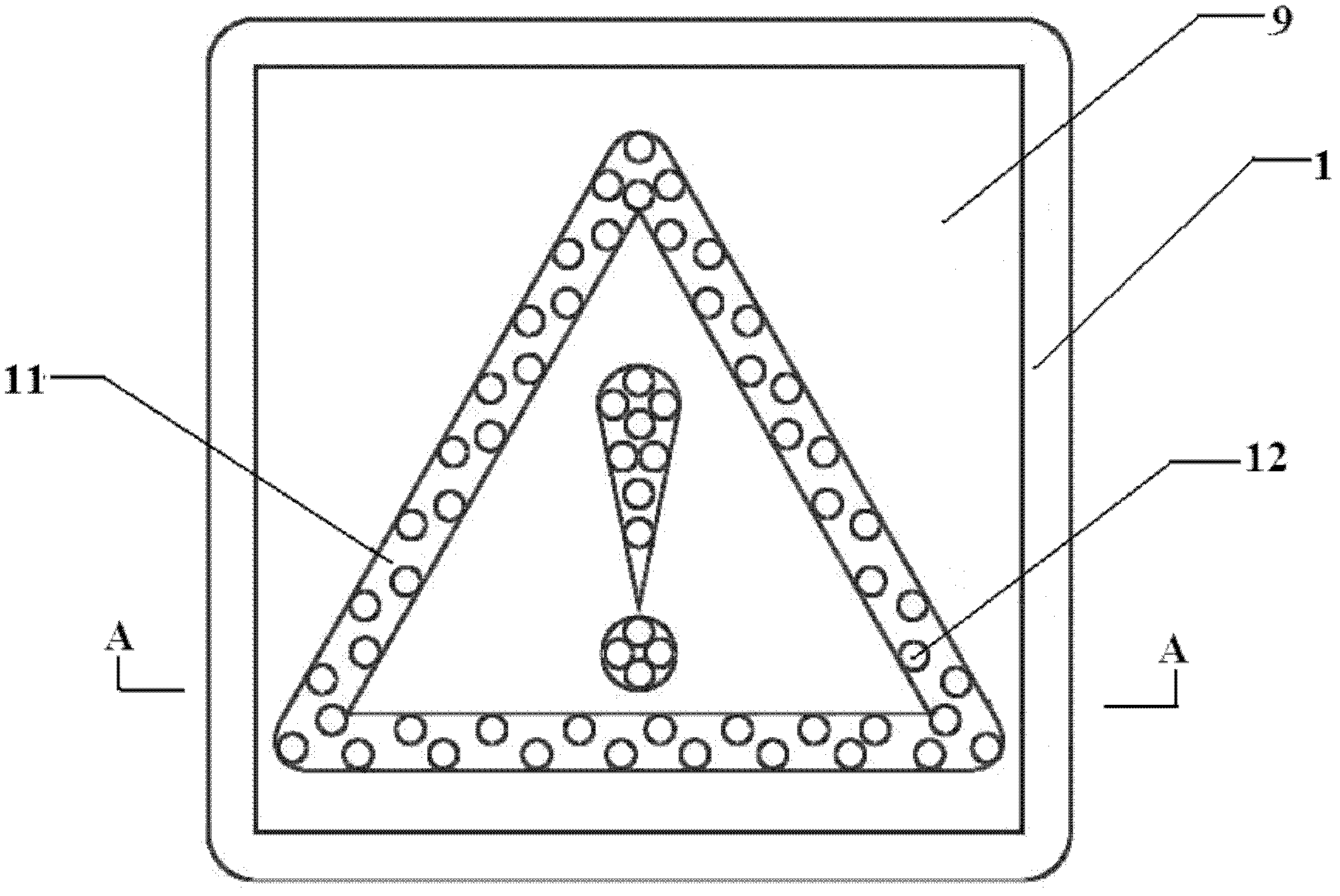
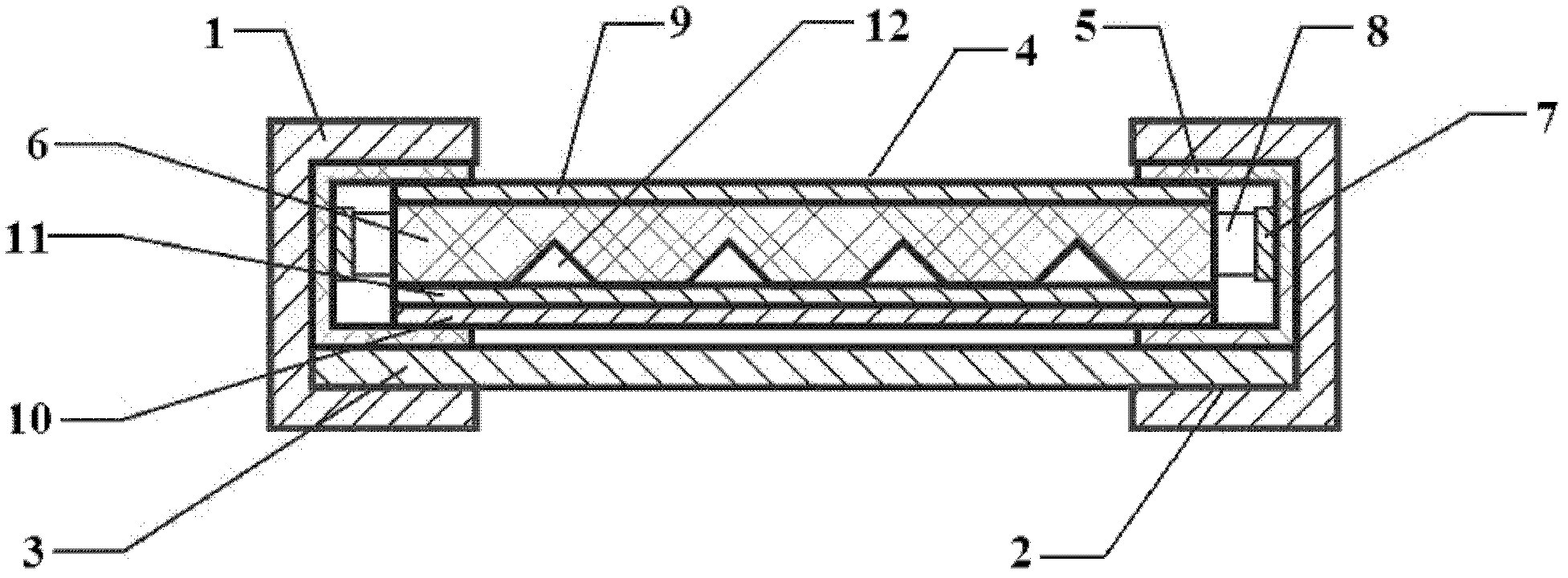
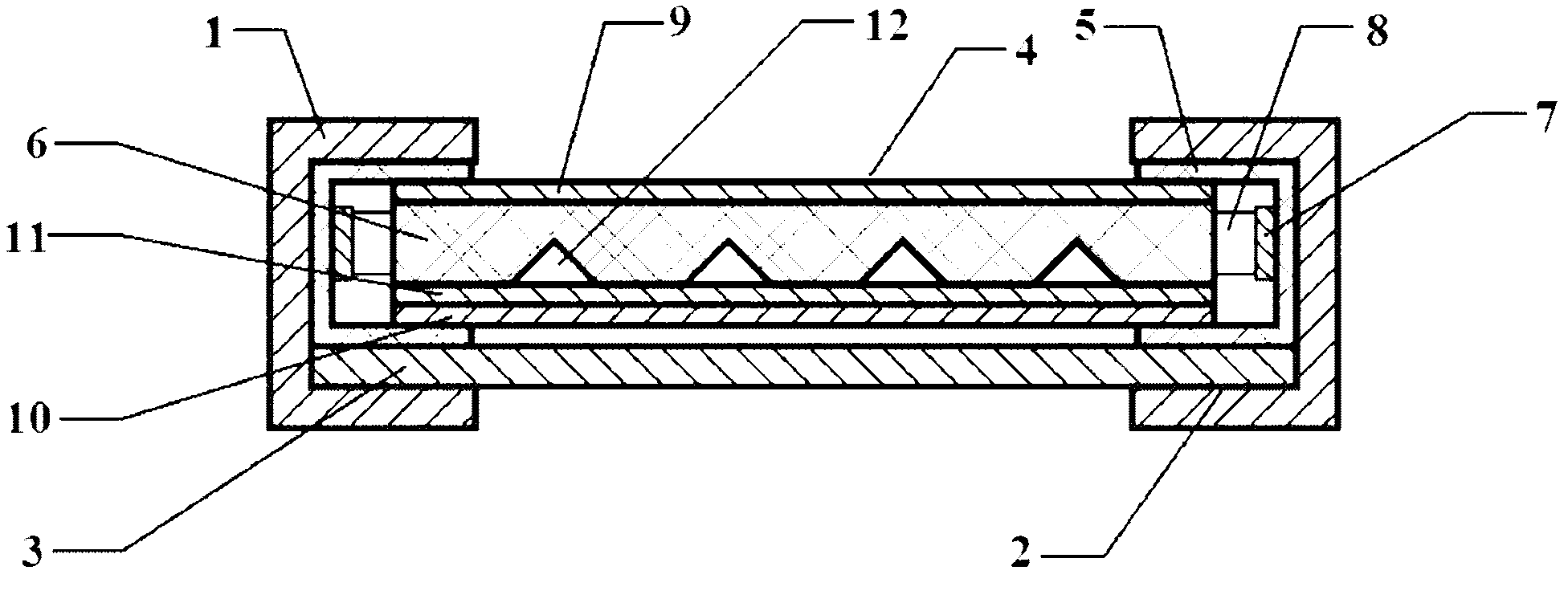
[0023] Such as Figure 1-2 As shown, a high-efficiency and low-power LED surface light source active and passive light-emitting warning device according to the embodiment of the present invention includes a warning device body, and an outer frame 1 and four outer frames 1 are respectively arranged around the warning device body. A card slot 2 is formed between them, the bottom end of the card slot 2 is provided with a substrate 3, a light emitting device 4 is connected to the substrate 3, and a car bag 5 is wrapped around the light emitting device 4; the light emitting device 4 includes a light guide plate 6, At least one side around the light plate 6 is provided with a strip circuit board 7, and a number of LED light-emitting diodes 8 are evenly arranged on the strip circuit board 7; The bottom end is provided with bottom high-reflectivity optical film 10, and the top surface of bottom high-reflectivity optical film 10 is pasted with the warning label that is made of retro-re...


PUM


Abstract

The invention relates to a high lighting-effect low power-consumption light-emitting diode (LED) area light source initiative-passive light-emitting alarm device, which comprises an alarm device body, wherein outer frames are respectively arranged on the periphery of the alarm device body, a clamping groove is formed among the four outer frames, a baseboard is arranged at the bottom end of the clamping groove, a light-emitting device is connected onto the baseboard, and a bag is wrapped on the periphery of the light-emitting device. The light-emitting device comprises a light guiding plate, a strip-shaped circuit board is formed on at least one side of the periphery of the light guiding plate, and a plurality of LEDs are evenly distributed on the strip-shaped circuit board. A first reverse-reflection optical film is bonded at the top end of the light guiding board, a bottom layer high reflection ratio optical film is arranged at the bottom end of the light guiding board, an alarm label formed by a second reverse-reflection optical film is bonded on the top surface of the bottom layer high reflection ratio optical film, and the strip-shaped circuit board is connected with an external power source adapter through leads. The high lighting-effect low power-consumption LED area light source driving and driven light-emitting alarm device has the advantages of being capable of not only initiatively emitting light and displaying alarm information clearly, but also passively emitting light by reflecting lights of an external power source in return mode and displaying alarm information clearly.

Description

technical field [0001] The invention relates to a warning device, in particular to an active and passive light-emitting warning device of an LED surface light source with high light efficiency and low power consumption. Background technique [0002] As a kind of safety facility, warning signs mainly remind people of matters that should be paid attention to in the form of patterns or words. At present, the warning signs that are commonly used and used mainly include: ordinary signs (non-luminous, non-reflective), reflective signs (reflective but not luminous), luminous signs (luminous but not reflective), and a small amount of LED light-emitting diodes installed on the surface of reflective signs glowing reflective sign. in: [0003] Ordinary signs can only be used during the day or in environments with very good lighting conditions because they can neither emit light nor reflect light. [0004] Reflective signs are generally engraved or printed with retro-reflective opti...

Claims


Application Information

Patent Timeline
Patent Type & Authority Applications(China)
IPC IPC(8): G08B5/36G09F13/22G09F13/16
Inventor 董飞鸿
Owner 董飞鸿
Why Eureka
Try Eureka