Card connector with removing function

A card connector and function technology, applied in the direction of connection, connecting device components, electrical components, etc., can solve the problems of reduced degree of freedom, larger occupied area of ​​the connector, and inability to ensure, and achieve the effect of miniaturization

Inactive Publication Date: 2012-07-18
SMK CO LTD
View PDF6 Cites 10 Cited by
  • Summary
  • Abstract
  • Description
  • Claims
  • Application Information

AI Technical Summary

Problems solved by technology

[0007] However, in the prior art as described above, since there is a take-out mechanism composed of a push-out arm and a push rod for operating the push-out arm, the overall shape of the connector, that is, relative to the board on which the connector is mounted The occupied area becomes larger, and there is also the problem that the degree of freedom of design decreases.
On the other hand, if the outer shape of the extrusion arm is reduced in order to realize the miniaturization of the connector, there is a problem that the length of the arm required to eject the card-shaped member with a sufficient extrusion amount cannot be ensured.
[0008] In addition, since the force exerted by the operator is transmitted to the push-out arm through the push rod when the card-shaped component is pushed out, if the operator exerts excessive force, the card-shaped component will jump out violently, which may cause damage to the card and the like. The problem
In addition, there is a problem that there is a risk that card-shaped parts such as trays will be pulled out due to impacts such as falling.
[0009] Furthermore, there is a problem that, due to the take-out mechanism, in such a connector, the number of parts increases and the cost increases accordingly.

Method used


Image

  • Card connector with removing function
  • Card connector with removing function
  • Card connector with removing function

Examples


Embodiment Construction

[0028] Next, embodiments of the card connector of the present invention will be described based on the examples shown in the drawings. In addition, reference numeral A denotes a card such as an IC card.

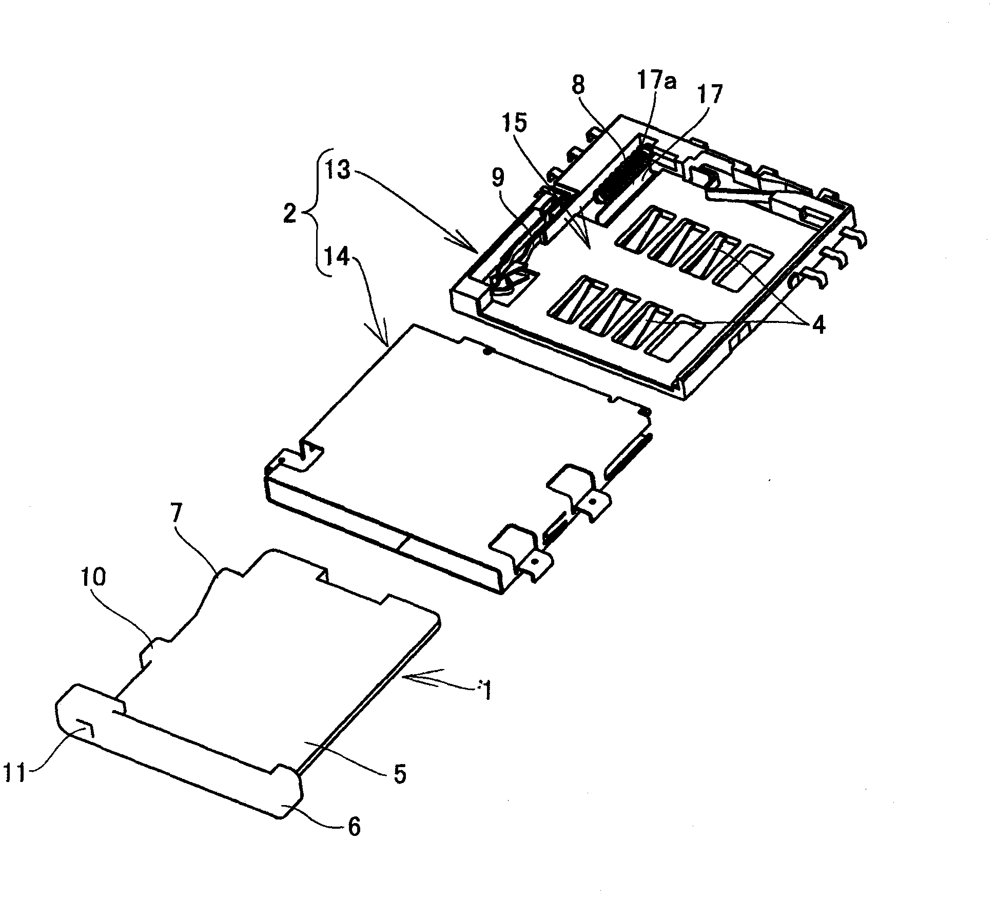
[0029] The card connector inserts the card tray 1 containing the card A into the housing 2, and the terminal parts 3, 3 ... arranged on one side of the card A and the contacts 4, 4. .. make contact elastically, and electrically connect the card A to the substrate provided with the housing 2 through the contacts 4 .

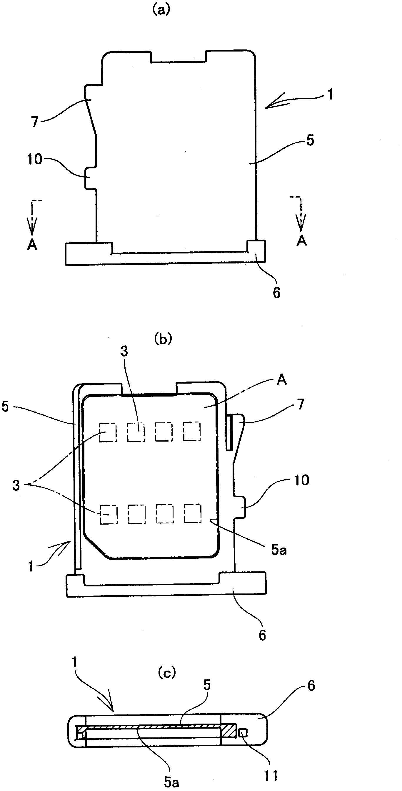
[0030] Such as figure 2 As shown, the card tray 1 has: a flat main body 5 having a card accommodating recessed portion 5a for accommodating the card A on one side; The resin material is integrally formed.

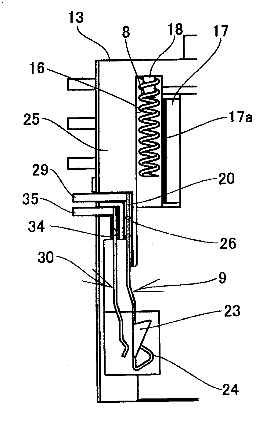
[0031] On the rear side of the side edge of the main body part 5, an urging part 7 is protrudingly provided, and the urging part 7 presses a return spring 8 described later in a compression direction as the card tray 1 is pushed in. In addition, an engage...


PUM


Abstract

The invention provides a card connector with a removing function. The card connector can act stable card removing operations, realize miniaturization, and can be manufactured with a low cost. A locking mechanism possesses a locking part at one side of a housing (2), wherein the locking part faces the access direction of a card type part (1). The locking part possesses the components as following: a fixing sheet portion fixed arranged on the housing (2); a spring sheet portion extended from one end of the fixing sheet portion to the access direction of the card type part; and a cooperation portion (32) supported at the front end of the spring sheet portion and detachably matched with the side edge portion of the card type part (1). The spring sheet portion possesses an operation convex portion utilizing an extraction operation part (8) to extract at the traverse direction, the convex portion is extruded with the insertion of the extraction operation part, the cooperation part acts at the direction released from the card type part.

Description

technical field [0001] The present invention relates to a card connector with a take-out function, which is used to connect a card such as an IC card on a substrate, and which can be taken out with a simple operation. Background technique [0002] Hitherto, among such card connectors, a card connector with a removal function is known in which a card such as an IC card or a card-shaped member such as a card tray accommodating the card can be taken out from a housing by operating a push rod (for example, Patent Document 1). [0003] For example, if Figure 10 As shown, the card connector with the function of taking out has a push-out arm 101 rotatably supported on the inner side of the housing 100 in the direction of card insertion and removal. By pressing one end of the push-out arm 101 with a push rod 102, the The push-out arm 101 is rotated, and the inner edge of the card tray 104 is pushed out in the discharge direction by the other end side 103 of the arm. [0004] prio...

Claims


Application Information

Patent Timeline
Patent Type & Authority Applications(China)
IPC IPC(8): H01R13/639H01R13/71H01R13/633H01R13/635H01R12/71
Inventor 佐佐木良德桥大辅
Owner SMK CO LTD
Why Eureka
Try Eureka