
Partial discharge two-in-one intelligent sensor

A smart sensor and two-in-one technology, applied in the field of sensors, can solve problems such as difficulty in disassembly, failure of primary power equipment, sensor failure, etc., and achieve the effects of easy maintenance and installation, guaranteed stability, and simple structure

Pending Publication Date: 2020-08-25
上海贤业电气科技有限公司
View PDF0 Cites 3 Cited by
  • Summary
  • Abstract
  • Description
  • Claims
  • Application Information

AI Technical Summary

Problems solved by technology

[0002] Switchgear is often used to place primary power equipment. If there is partial discharge in the primary power equipment in the switchgear and it is not discovered in time, it may lead to failure of the primary power equipment, thereby affecting the stability and reliability of the grid operation. influences
The measurement data of partial discharge on-line monitoring is one of the important indicators for judging the operating conditions of power primary equipment. Usually, partial discharge sensors are used to carry out online monitoring of partial discharge of power primary equipment. The existing transient ground voltage / ultrasonic combination An intelligent sensor has both ultrasonic detection and transient ground voltage detection functions. The sensor is installed inside the device. During the long-term use of the sensor, when the sensor is damaged inside, the sensor will fail. At this time, the sensor needs to be disassembled and repaired. For detection and maintenance, but due to the complex structure of the sensor installation, it is difficult to disassemble, take out and install again, and the installation structure needs to be improved

Method used


Image

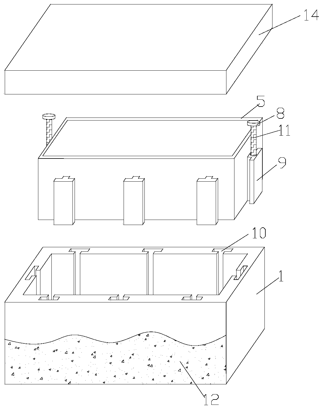
  • Partial discharge two-in-one intelligent sensor
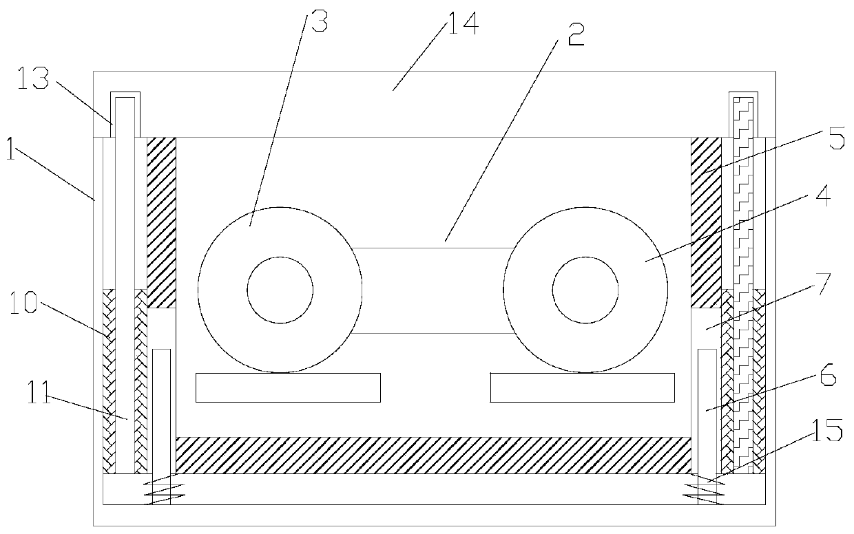
  • Partial discharge two-in-one intelligent sensor
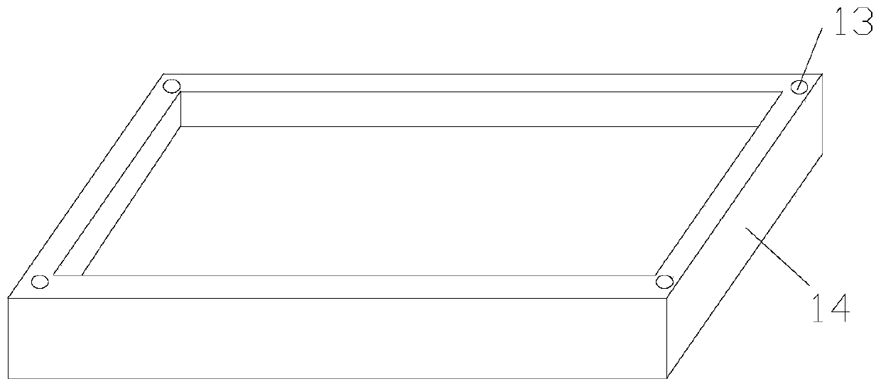
  • Partial discharge two-in-one intelligent sensor

Examples


Embodiment Construction

[0018] The following will clearly and completely describe the technical solutions in the embodiments of the present invention with reference to the accompanying drawings in the embodiments of the present invention. Obviously, the described embodiments are only some, not all, embodiments of the present invention. Based on the embodiments of the present invention, all other embodiments obtained by persons of ordinary skill in the art without making creative efforts belong to the protection scope of the present invention.

[0019] In the description of the present invention, it should be noted that the orientation or positional relationship indicated by the terms "vertical", "upper", "lower", "horizontal" etc. is based on the orientation or positional relationship shown in the drawings, and is only In order to facilitate the description of the present invention and simplify the description, it does not indicate or imply that the device or element referred to must have a specific o...


PUM


Abstract

The invention relates to the field of sensors, and particularly discloses a partial discharge two-in-one intelligent sensor, which comprises a protective shell and a two-in-one detection mechanism installed in the protective shell. A sealing cover is arranged at the top end of the protective shell. The two-in-one detection mechanism is sleeved with an integrated positioning installation box with an upward opening, and the two-in-one detection mechanism is poured in the positioning installation box through an insulating material. Positioning sliding rods are arranged at the corners of the periphery of the lower surface of the positioning installation box, the bottoms of the positioning sliding rods are fixedly connected with the bottom of the protective shell, and the bottoms of the positioning sliding rods are sleeved with damping springs. A first sliding groove allowing the positioning sliding rod to slide up and down is formed in the position, corresponding to the positioning slidingrod, of the positioning installation box. Sliding blocks of a T-shaped structure are installed on the side walls of the periphery of the positioning installation box. When the intelligent sensor is overhauled, the intelligent sensor can be stably taken out by hand only by reversely rotating the screw rod by hand.

Description

technical field [0001] The invention relates to the field of sensors, in particular to a partial discharge two-in-one intelligent sensor. Background technique [0002] Switchgear is often used to place primary power equipment. If there is partial discharge in the primary power equipment in the switchgear and it is not discovered in time, it may lead to failure of the primary power equipment, thereby affecting the stability and reliability of the grid operation. influences. The measurement data of partial discharge on-line monitoring is one of the important indicators for judging the operating conditions of power primary equipment. Usually, partial discharge sensors are used to carry out online monitoring of partial discharge of power primary equipment. The existing transient ground voltage / ultrasonic combination An intelligent sensor has both ultrasonic detection and transient ground voltage detection functions. The sensor is installed inside the device. During the long-ter...

Claims


Application Information

Patent Timeline
Patent Type & Authority Applications(China)
IPC IPC(8): G01R31/12G01R1/04
CPCG01R1/04G01R31/1209G01R31/1227
Inventor 李建华陈华玲陈建文
Owner 上海贤业电气科技有限公司
Learn More