Knee prosthesis

A knee joint prosthesis and a knee joint technology are applied in the field of knee joint prostheses, which can solve the problems of lack of guiding structure and inability to control joint movement in a normal mode, and achieve the effect of convenient production.

Active Publication Date: 2012-07-18
厄斯·威斯 +2
View PDF6 Cites 9 Cited by
  • Summary
  • Abstract
  • Description
  • Claims
  • Application Information

AI Technical Summary

Problems solved by technology

However, these knees without cruciate ligaments lack the guiding structures to control joint movement in the normal pattern

Method used


Image

  • Knee prosthesis
  • Knee prosthesis
  • Knee prosthesis

Examples


example

[0079] --refer to Figure 9 with Figure 10 , the radii Re and Ri can be made larger. As the flexion angle increases, the envelope of slack moves from anterior to posterior. With more slack in the middle of the flexion movement and less slack (more stability) at small and large flexion angles, the width of the envelope of slack changes accordingly.

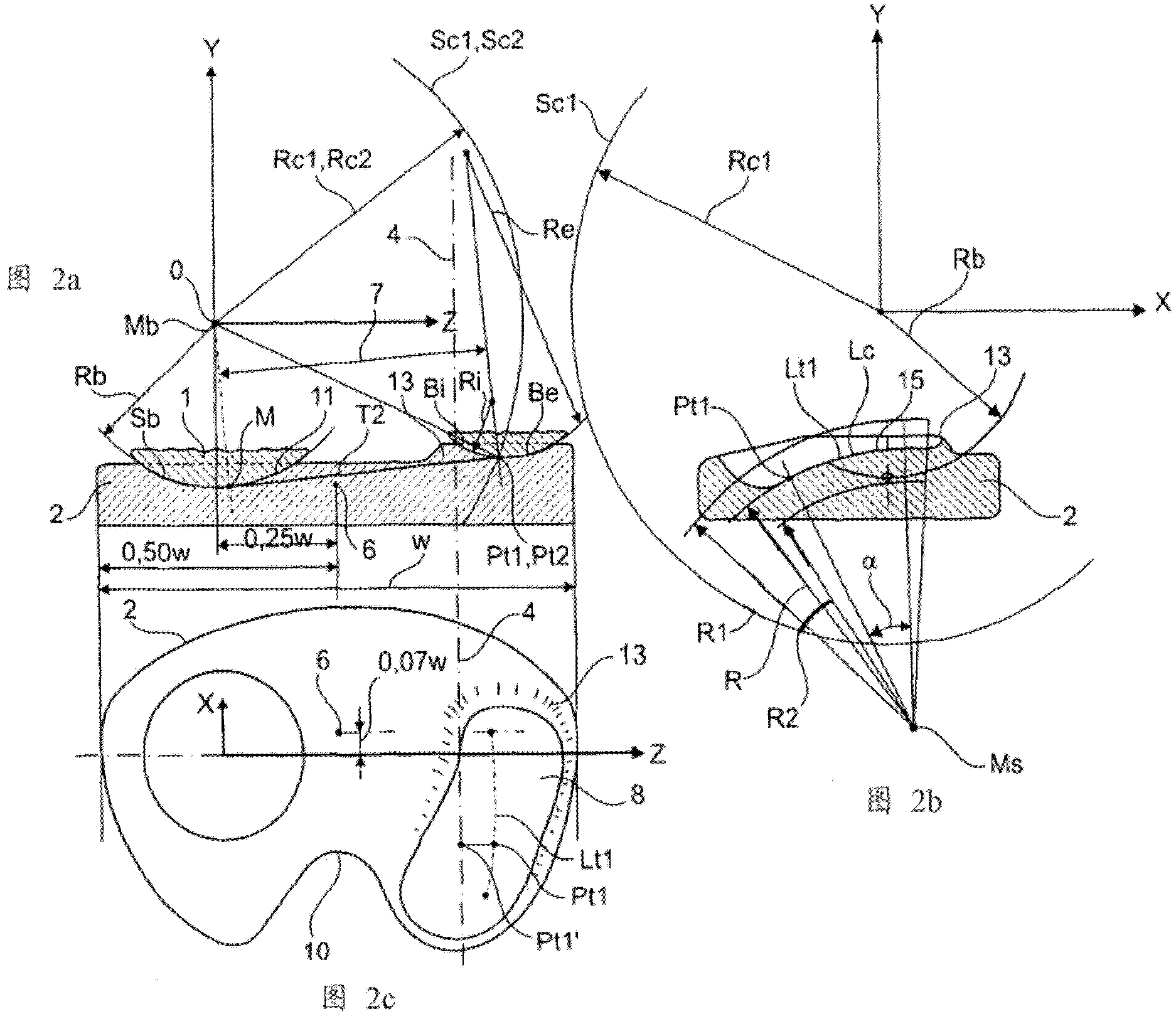
[0080] --refer to Image 6 In the example shown, in the middle of the flexion movement, the guide curves Be and Bi may undergo a slight shift in the direction of the tangent T2 in the plane E1; the spherical radius Rc of the outer guide curve Be is larger and the spherical radius Rc of the inner guide curve Bi is smaller . If a third straight line segment is added between the two guide curves, then as the slack increases, the joint may just fall on the third line segment without joining the two guide curves.

[0081] If the material used is sufficiently elastic, the trajectory line Lt1 or the third line segment can be deflect...


PUM


Abstract

A knee prosthesis for a knee joint with a medial ball- like femoral condyle and with a width "w" is characterized on the lateral compartment by: - a trace-line "Lt1" of contact points "Pt1" for the tibia component (2) as a predetermined curve (15 ) on a spherical surface "Sc1", which has its centre at the centre Mb of the medial ball 1 and which has a radius in the range "Rc1" = 0.65 w + / - 0.25 w - a trace-line "Lt2" of common contact points "Pt2" at given flexion angles gamma for a similar spherical surface "Sc2" attached to the femoral component with radius "Rc2"= Rc1, whereby at a given flexion angle gamma there exists a plane "E1" through the centre Mb and the common contact point Pt1 / Pt2, which contains the same guiding curves "Bi", "Be" on the tibial and on the femoral components, "Bi" towards medial and "Be" towards lateral, both of which stay in a geometrically fixed relation to the common contact point Ptl / Pt2, and - guiding curves "Bi" and "Be", which generate an enforced gliding and rolling movement in both directions.

Description

technical field [0001] The present invention encompasses a knee prosthesis for use in a knee joint of width "w" and having a bulbous femoral condyle and corresponding tibial socket on the medial side, the articular ball and socket having a center "Mb", radius "Rb" and spherical "Sb" and define an X, Y, Z Cartesian coordinate system attached to the tibia with origin "O" at center "Mb". Background technique [0002] The difference in functional performance between normal knees and knees undergoing total knee replacement (TKR) has been thought to be related to the different movement patterns of the normal and artificial knees (Victor, Berlemans, 2006; T.P. Andieriage, C.O. Delbye, 2005). The medial axis knee has a contoured ball-and-socket structure in the medial compartment of the joint that replicates the anatomy of the normal knee and accommodates natural patterns of motion. However, these knee joints without cruciate ligaments lack the guiding structures to control joint ...

Claims


Application Information

Patent Timeline
Patent Type & Authority Applications(China)
IPC IPC(8): A61F2/38
CPCA61F2250/0039A61F2002/30327A61F2/38A61F2/3859A61F2230/0093A61F2230/0095A61F2/3836A61F2/389
Inventor 厄斯·威斯沙哈姆·阿米里希欧多尔·德里克·弗农·库克
Owner 厄斯·威斯
Why Eureka
Try Eureka