Polishing unit and polishing method by polishing unit

A grinding method and a technology of a grinding device, which are applied to machine tools suitable for grinding workpiece edges, grinding machines, surface polishing machine tools, etc., can solve the problems of lack of interchangeability between cover and main body, excessive space, and difficulty in pressing force control in a certain direction, etc.

Active Publication Date: 2012-07-18
SINTOKOGIO LTD
View PDF10 Cites 4 Cited by
  • Summary
  • Abstract
  • Description
  • Claims
  • Application Information

AI Technical Summary

Problems solved by technology

Therefore, if the main body 111 and the cover 112 do not match, the amount of space may exceed the specified range, so the main body 111 and the cover 112 do not have the interchangeability with respect to other covers and the main body, and there is a problem that the drum groove cannot be effectively carried out. 110 disass

Method used


Image

  • Polishing unit and polishing method by polishing unit
  • Polishing unit and polishing method by polishing unit
  • Polishing unit and polishing method by polishing unit

Examples


Embodiment Construction

[0037] Next, the grinding unit used in the centrifugal drum grinding device of the present invention will be described. However, the present invention is not limited to the following embodiments.

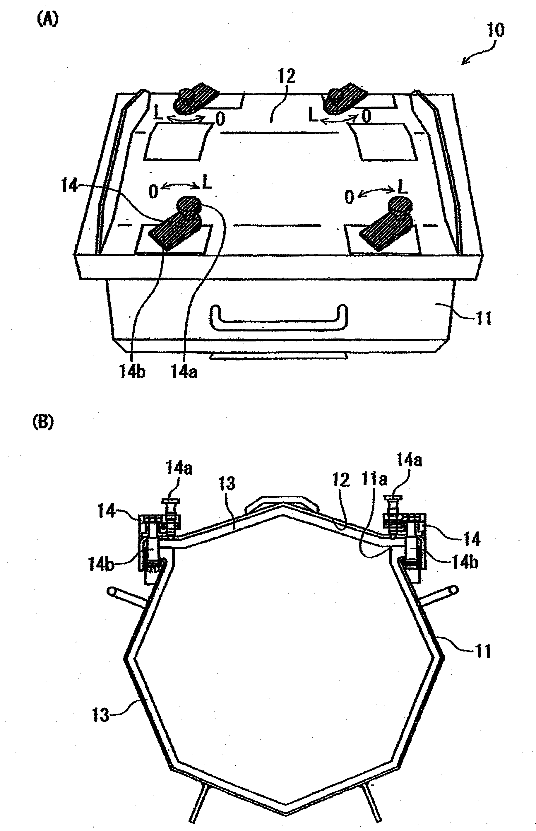
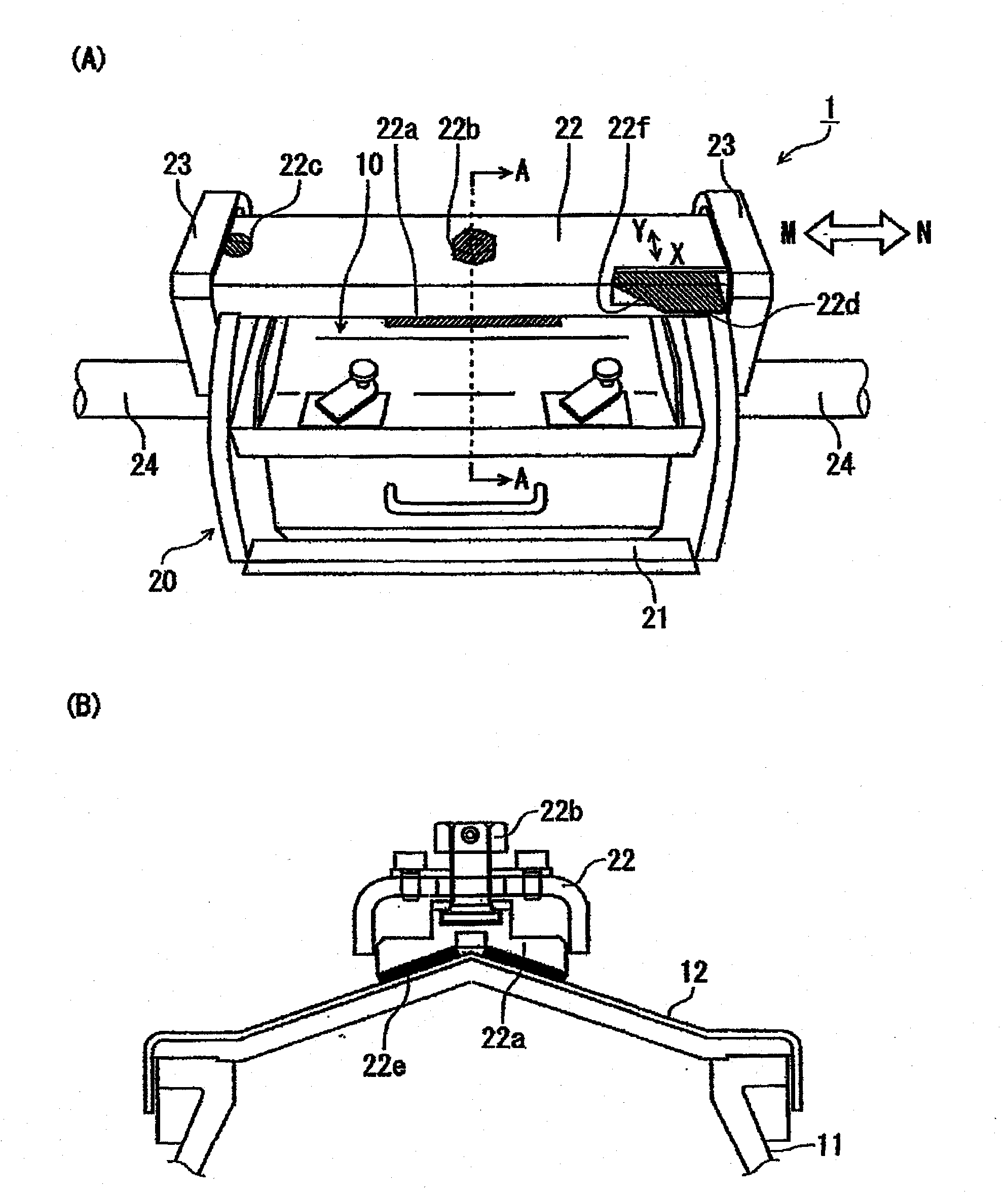
[0038] Such as figure 1 As shown, the drum tank 10 is formed into a cylindrical shape with a polygonal or circular longitudinal section, and includes a main body 11 and a cover 12 that seals the opening 11. The opening 11a. In this embodiment, as an example, the longitudinal cross-sectional shape of the drum tank 10 is formed in an octagon.

[0039] On the inner surface of the main body portion 11 and the lower surface of the cover portion 12, a liner 13 made of a wear-resistant rubber member is formed to prevent abrasion of the respective surfaces, as in a conventional polishing unit.

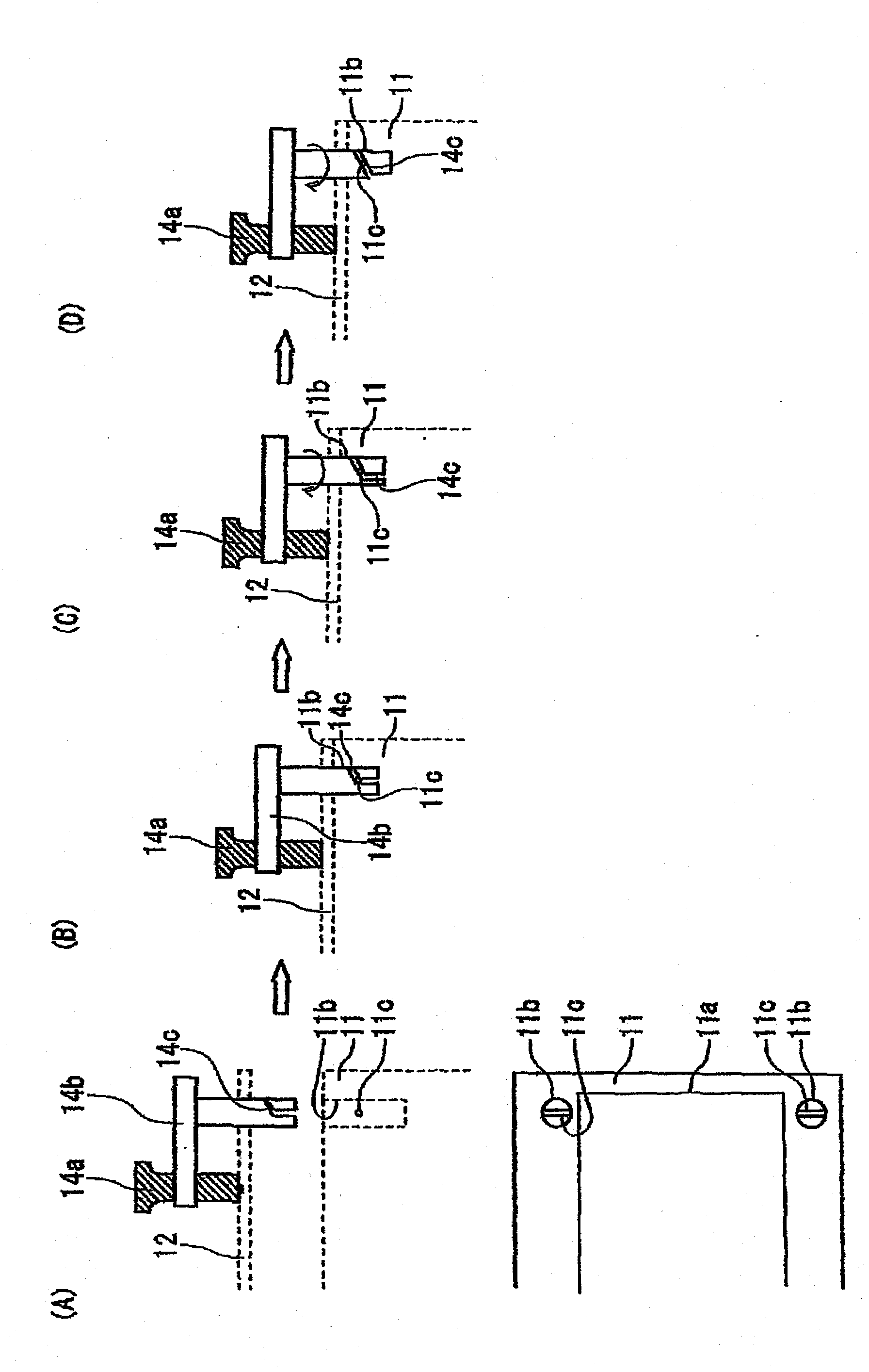
[0040] Cover fixing members 14 for fixing the cover 12 to the main body 11 are provided at four places on the cover 12 corresponding to fixing positions (holes 11 b ) outside the opening 11 a of...


PUM


Abstract

Disclosed is a polishing unit wherein a main body part (11) and a lid (12) of a barrel tank (10) are respectively interchangeable, and the lid (12) and the barrel tank (10) can be reliably secured to the main body part (11) of the barrel tank (10) and the barrel tank case (20), respectively. The barrel tank (10) has a lid securing member (14) for securing the lid (12) to the main body part (11). The barrel tank case (20) includes a tray (21) for mounting and holding the barrel tank (10) thereon, a barrel tank securing member (22) for securing the barrel tank (10) to the tray (21), and a pair of guide parts (23) capable of moving the barrel tank securing member (22) in a horizontal direction. The barrel tank securing member (22) includes a pressing member (22a) which is placed over a position facing the tray (21) so as to be able to press the barrel tank (10) vertically downward and presses the barrel tank (10), and, as a positioning member which when the barrel tank securing member (22) is mounted, restricts the movement of the barrel tank securing member (22) using the guide parts (23) as a reference, a convex member (22c) and a protruding member (22d).

Description

technical field [0001] This application claims the priority of Japanese Patent Application No. 2010-216294 (filing date: September 28, 2010), title of the invention "grinding unit", and the entire content of this application is incorporated in this specification by reference. [0002] The present invention relates to a grinding unit used in a centrifugal drum grinding device and a grinding method of a centrifugal drum grinding device equipped with the grinding unit. Background technique [0003] For a long time, in order to deburr, fillet, polish and grind the object to be ground (workpiece), the following centrifugal drum grinding device has been widely used: put the workpiece and grinding media in the drum groove, and make the drum groove Since it revolves, the grinding medium flows to grind the workpiece. [0004] A conventional polishing unit used in such a centrifugal barrel polishing device is disclosed in Patent Document 1, for example. [0005] Figure 4 An example...

Claims


Application Information

Patent Timeline
IPC IPC(8): B24B31/02B24B31/12
CPCB24B31/104B24B31/12
Inventor 田中槙二德升智宏羽鸟左一郎加岛慎也
Owner SINTOKOGIO LTD
Why Eureka
Try Eureka