Method for manufacturing stacked rotor core

A manufacturing method and core technology, applied in the manufacture of motor generators, stator/rotor bodies, magnetic circuit rotating parts, etc., can solve problems such as hindering preparation time and shortening, and achieve improved rigidity, extended life, and plate thickness. thin effect

Active Publication Date: 2012-07-18
MITSUI HIGH TEC INC
View PDF5 Cites 13 Cited by
  • Summary
  • Abstract
  • Description
  • Claims
  • Application Information

AI Technical Summary

Problems solved by technology

[0003] However, in this processing method, resin that has hardened after injection adheres and remains on the surface of the core main body, and a process of removing the remaining resin is required, which hinders shortening of preparation time.

Method used


Image

  • Method for manufacturing stacked rotor core
  • Method for manufacturing stacked rotor core
  • Method for manufacturing stacked rotor core

Examples


Embodiment Construction

[0058] Next, an embodiment of the present invention will be described with reference to the drawings so that the present invention can be understood.

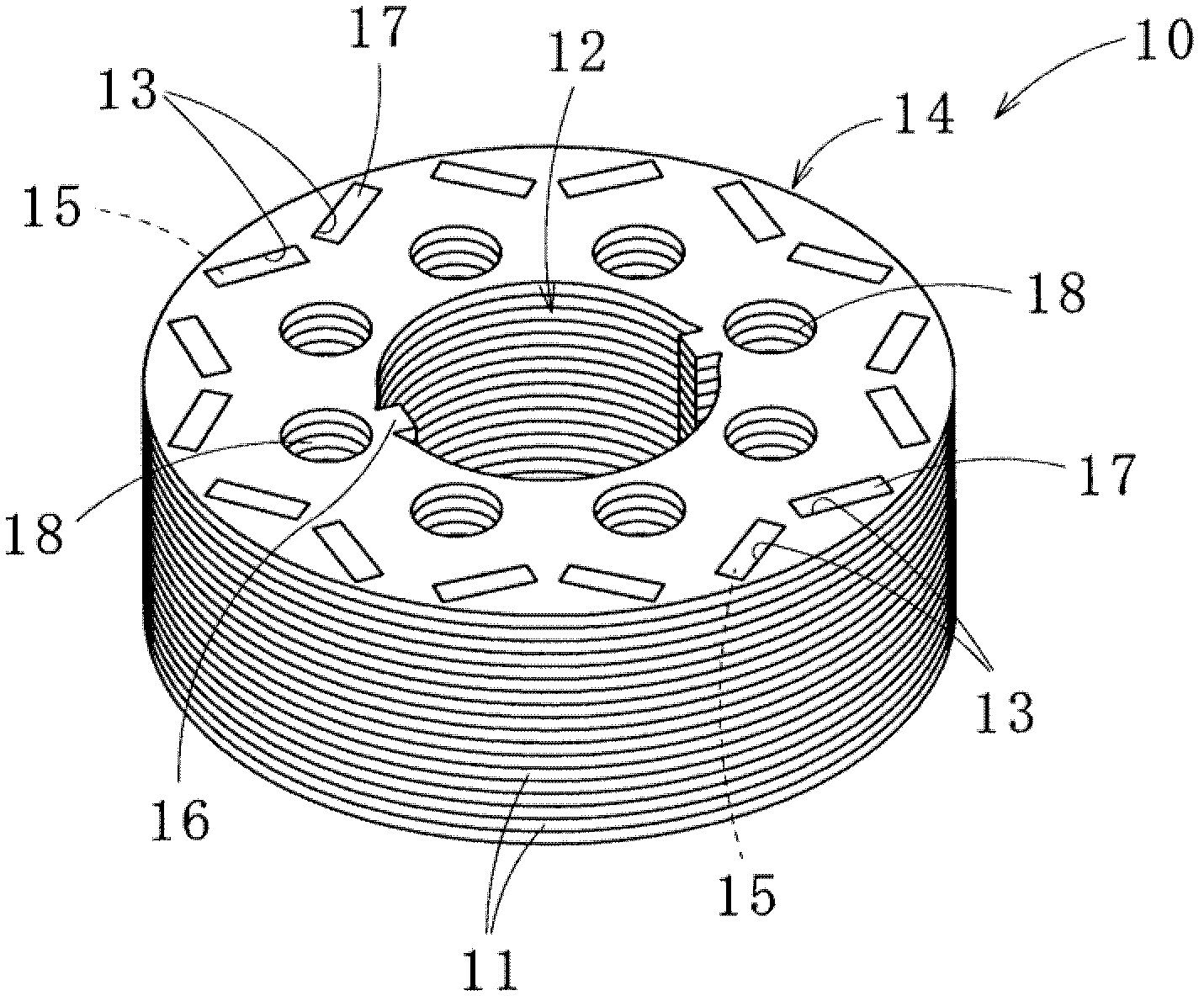
[0059] First, refer to figure 1 , figure 2 A laminated rotor core (hereinafter also simply referred to as a rotor core) 10 manufactured by the method for manufacturing a laminated rotor core according to the first embodiment of the present invention will be described.

[0060] The rotor core (rotor) 10 is formed by stacking a plurality of core pieces 11, and the core body 14 has a plurality of magnet insertion holes (an example of a magnet insertion part) 13 formed around a central shaft hole 12, and the magnets inserted into the core body 14 are A permanent magnet 15 is inserted into the hole 13 .

[0061] The core piece 11 constituting the core main body 14 is a ring-shaped core piece punched from an electrical steel sheet having a thickness of, for example, about 0.5 mm or less (specifically, 0.15 to 0.5 mm). Furthermor...


PUM


Abstract

A method for manufacturing a stacked rotor core (10) is performed in such a manner that a permanent magnet (15) is inserted in each magnet insertion section (13) of the core body (14) formed by stacking core pieces (11) and then the permanent magnet (15) is affixed by filling the magnet insertion section (13) with a resin (17) from a resin storage section (19) provided to molds for sandwiching and holding the core body. The method has: a first step for disposing divided dummy plates (21) between the core body (14) and a mold, the divided dummy plates (21) each covering one or more magnet insertion sections (13) and having resin pouring holes (28) communicating with the magnet insertion sections (13); a second step for pouring the resin (17) into the magnet insertion sections (13) from the resin storage section (19) through the resin pouring holes (28) provided in the divided dummy plates (21) and corresponding to the magnet insertion sections (13); and a third step for removing the divided dummy plates (21) together with an excess resin (34) after the resin (17) inserted in the magnet insertion sections (13) is hardened. In the method, the easiness of the resin sealing work is improved.

Description

technical field [0001] The present invention relates to a method of manufacturing a laminated rotor core in which permanent magnets inserted into a plurality of magnet insertion portions are fixed with resin. Background technique [0002] Conventionally, there is a magnet molding method as a method for fixing permanent magnets (magnets) to a core body of a laminated rotor core (rotor core) used in a motor. This processing method heats the core body in which the permanent magnet is placed in the magnet insertion part (magnet insertion hole), and when it reaches a certain temperature, injects molding resin into the magnet insertion part and heats it to harden it. , so as to fix the permanent magnet on the core body. [0003] However, in this processing method, resin hardened after injection adheres and remains on the surface of the core main body, and a step of removing the remaining resin is required, which hinders shortening of preparation time. [0004] Therefore, a metho...

Claims


Application Information

Patent Timeline
Patent Type & Authority Applications(China)
IPC IPC(8): H02K15/03H02K1/27
CPCH02K15/03H02K1/276
Inventor 长井亮荒添萌加藤刚
Owner MITSUI HIGH TEC INC
Why Eureka
Try Eureka