
Image capturing device, adjusting device, and optical axis adjusting system for image capturing device

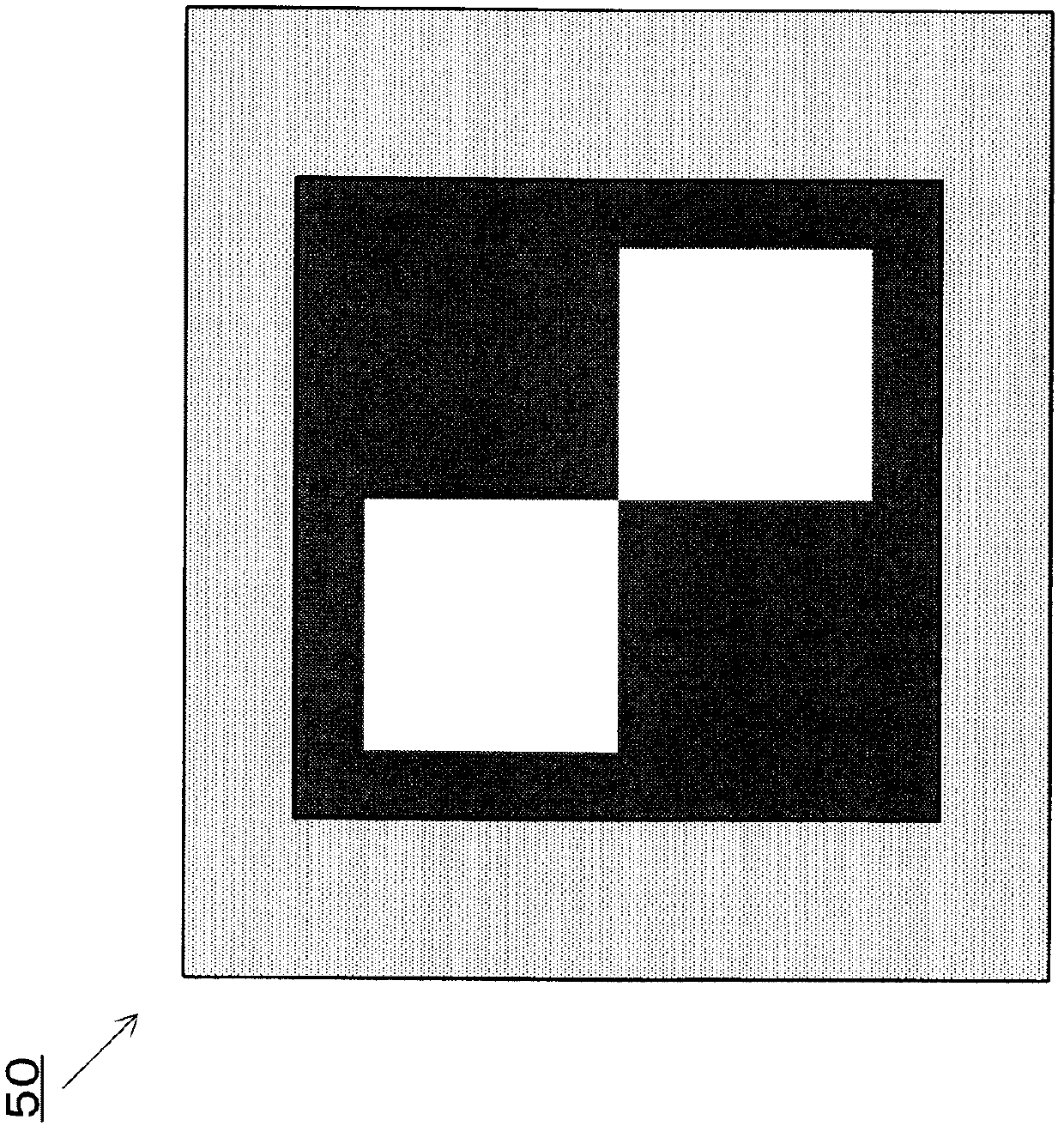
A technology of camera device and adjustment system, which is applied in parts of TV system, image communication, parts of color TV, etc. It can solve the problem of inability to accurately detect the boundary line between white and black parts and the inability to adjust the optical axis accurately Problems such as wrong detection of position and center position

Inactive Publication Date: 2012-07-18
TOYOTA JIDOSHA KK
View PDF2 Cites 0 Cited by
  • Summary
  • Abstract
  • Description
  • Claims
  • Application Information

AI Technical Summary

Problems solved by technology

At this time, the white part of the target may be saturated (so-called halo), and the white part of the captured image may be captured in a state that is wider than the actual area.
In such a case, the boundary line between the white part and the black part cannot be accurately detected, which may cause the center position of the target to be detected incorrectly
In addition, if the optical axis is adjusted so that the optical axis coincides with the center position of the erroneously detected target, the optical axis may not be adjusted to the correct position.

Method used


Image

  • Image capturing device, adjusting device, and optical axis adjusting system for image capturing device
  • Image capturing device, adjusting device, and optical axis adjusting system for image capturing device
  • Image capturing device, adjusting device, and optical axis adjusting system for image capturing device

Examples


no. 1 Embodiment approach

[0037] Refer below Figure 1 to Figure 6 , the imaging device 10 and the optical axis adjustment system 1 of the imaging device according to the first embodiment of the present invention will be described.

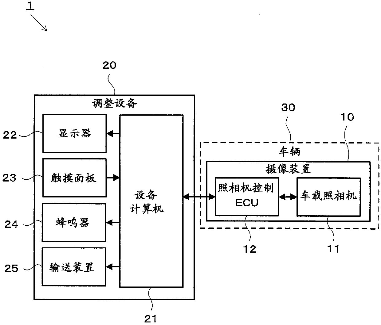
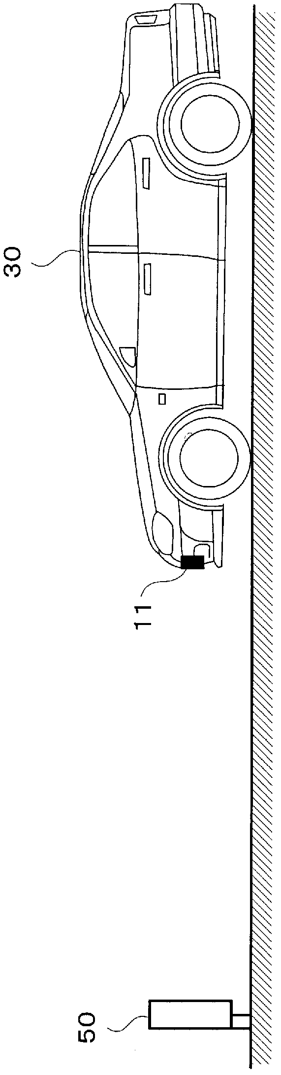
[0038] First, refer to figure 1 The configuration of the optical axis adjustment system 1 will now be described. in, figure 1 It is a block diagram showing the configuration of the optical axis adjustment system 1 according to the first embodiment. Such as figure 1 As shown, the optical axis adjustment system 1 is composed of an imaging device 10 and an adjustment device 20 . The imaging device 10 includes a vehicle-mounted camera 11 and a camera control ECU 12 . Moreover, the adjustment facility 20 is equipped with the facility computer 21, the liquid crystal display 22, the touch panel 23, the buzzer 24, and the conveyance apparatus 25. Hereinafter, an example in which the imaging device 10 is mounted on the vehicle 30 will be described.

[0039] The vehicle-mount...

no. 2 Embodiment approach

[0069] In the above-mentioned first embodiment, an example in which the adjustment set value TA is stored and changed in the adjustment device 20 has been described, but the adjustment set value TA may be stored and changed by a device mounted on the vehicle 30. value. Next, the imaging device 40 according to the second embodiment will be described.

[0070] Such as Figure 7 As shown, the imaging device 40 according to the second embodiment includes a vehicle-mounted camera 60 , a camera control ECU 61 , a display 62 , a touch panel 63 , and a buzzer 64 . Figure 7 It is a block diagram showing the configuration of the imaging device according to the second embodiment. Among them, the imaging device 40 is mounted on the vehicle 30 .

[0071] The on-vehicle camera 60 , camera control ECU 61 , display 62 , touch panel 63 , and buzzer 64 are the same hardware as the display 22 , touch panel 23 , and buzzer 24 according to the first embodiment. However, camera control ECU 61 ...


PUM


Abstract

Provided are an image capturing device which enables optical axis adjustment with accuracy, and an optical axis adjusting system for the image capturing device. Specifically provided is an optical axis adjusting system for an image capturing device, said optical axis adjusting system performing optical axis adjustment for the image capturing device that is mounted in a vehicle and captures an image of the periphery of the vehicle, and being provided with the image capturing device and an adjusting device connected to the image capturing device so as to be able to communicate therewith. The image capturing device comprises a parameter setting means which (A) under normal conditions, automatically sets the setting parameter for image capturing to a value corresponding to the brightness of an image capture environment, and (B) when the optical axis adjustment is executed, sets the setting parameter to a predetermined adjustment set value, a set value receiving means which receives the adjustment set value from the adjusting device when the optical axis adjustment is started, and an optical axis adjusting means which adjusts the optical axis on the basis of the image captured in the state where the setting parameter is set to the adjustment set value. The adjusting device comprises a set value storing means which previously stores the adjustment set value, and a set value transmitting means which transmits the adjustment set value to the image capturing device.

Description

technical field [0001] The present invention relates to an imaging device, an adjustment device, and an optical axis adjustment system for an imaging device, and more specifically, to an imaging device, an adjustment device, and an optical axis adjustment system for an imaging device that adjust an optical axis based on an image obtained by imaging a target . Background technique [0002] In recent years, there are vehicles equipped with cameras for acquiring images around the vehicle. For example, a camera for acquiring an image ahead of the vehicle is mounted for purposes such as lane recognition and preceding vehicle recognition. When such a camera is mounted on a vehicle, an installation error may occur in the direction of the optical axis of the camera with respect to the traveling direction of the vehicle due to mechanical or control technology reasons. When there is an error in the direction of the optical axis of the camera, the focus may be misaligned, or a desire...

Claims


Application Information

Patent Timeline
Patent Type & Authority Applications(China)
IPC IPC(8): H04N5/225H04N5/232H04N5/238
CPCH04N5/2351H04N5/23216H04N5/232H04N23/60H04N23/62H04N23/71
Inventor 宇佐美祐之影山潮矢小岛圭悟
Owner TOYOTA JIDOSHA KK
Learn More