Projection lens manufacturing apparatus, projection lens manufacturing method, projection lens manufactured by the projection lens manufacturing method and projector having the projection lens

A projection lens and manufacturing device technology, applied in projection devices, installation, optics, etc., can solve the problems of increased number, difficult fine-tuning, light source offset, etc., and achieve the effects of reducing manufacturing costs, easy fine-tuning, and high-precision adjustment

Inactive Publication Date: 2005-03-09
SEIKO EPSON CORP
View PDF4 Cites 9 Cited by
  • Summary
  • Abstract
  • Description
  • Claims
  • Application Information

AI Technical Summary

Problems solved by technology

[0009] However, in the prior art, in the method of adjusting the position of the lens by providing pin members on the projection lens itself as a product, the number of members constituting the projection lens increases, the cost of the projection lens increases, and at the same time, there is a problem that it cannot be miniaturized. and lightweight issues
[0010] In addition, when adjusting the in-plane position of the lens in three directions, when moving one pin member forward and backward, the other two pin members must also be moved forward and backward. Since it is difficult to know which of the two pin members needs to be moved, In other words, it is difficult to know the relationship between the advance and retreat of the pin member and the movement direction of the lens, so the operation of adjusting the optical axis position becomes very complicated.
At this time, since the advance and retreat directions of each pin member are different, it is necessary to increase the opening size of the position adjustment hole to some extent depending on the lens to be adjusted. Leakage of the light beam, etc., may reduce the quality of the projected image
[0011] Furthermore, in the method described in Patent Document 1, since the lens holding cylinder is moved, the fixed lens fixed to the lens holding cylinder is moved along with the movement of the lens holding cylinder, which may cause the center of the fixed lens to be adjusted relative to the Offset with light source
In this case, it is difficult to align the optical axis of the fixed lens with the optical axis of the lens to be adjusted, and sometimes the position of the optical axis of the lens cannot be adjusted with high precision.
[0012] Furthermore, in the method described in Patent Document 2, since it is necessary to provide a deformation absorbing portion on the lens holding tube, there is a problem of increasing the size of the lens holding tube and the projection lens provided with the lens holding tube.
In addition, since the deformation generated in the deformation absorbing part is eliminated by heating, plastics with poor heat resistance cannot be used as the material of the lens.
In addition, since the adjustment of the position of the lens fixed to the lens holding tube becomes the adjustment of the position of the lens against the holding force of the lens holding tube, it is difficult to perform fine adjustment, and it becomes difficult to adjust the optical axis position of the lens with high precision. difficult possibility
[0013] In addition, in the method described in Patent Document 3, since a position adjustment mechanism composed of a lens holding spring and a screw is provided on the projection lens, there is a problem that the number of components constituting the projection lens is increased, and the structure of the projection lens is complicated.
Furthermore, since such a position adjustment mechanism composed of a lens holding spring and a screw is provided on the projection lens side, it is necessary to make a structure with two lens holding cylinders consisting of a first lens holding cylinder and a second lens holding cylinder. To fix the first lens holding tube to the second lens holding tube, it is necessary to set a pressure ring at the front end of the first lens holding tube, and there is a problem that the projection lens is enlarged along the optical axis

Method used


Image

  • Projection lens manufacturing apparatus, projection lens manufacturing method, projection lens manufactured by the projection lens manufacturing method and projector having the projection lens
  • Projection lens manufacturing apparatus, projection lens manufacturing method, projection lens manufactured by the projection lens manufacturing method and projector having the projection lens
  • Projection lens manufacturing apparatus, projection lens manufacturing method, projection lens manufactured by the projection lens manufacturing method and projector having the projection lens

Examples


Embodiment Construction

[0089] 1. The first form of implementation

[0090] Next, a first embodiment of the present invention will be described based on the drawings.

[0091] [1. The main structure of the projector]

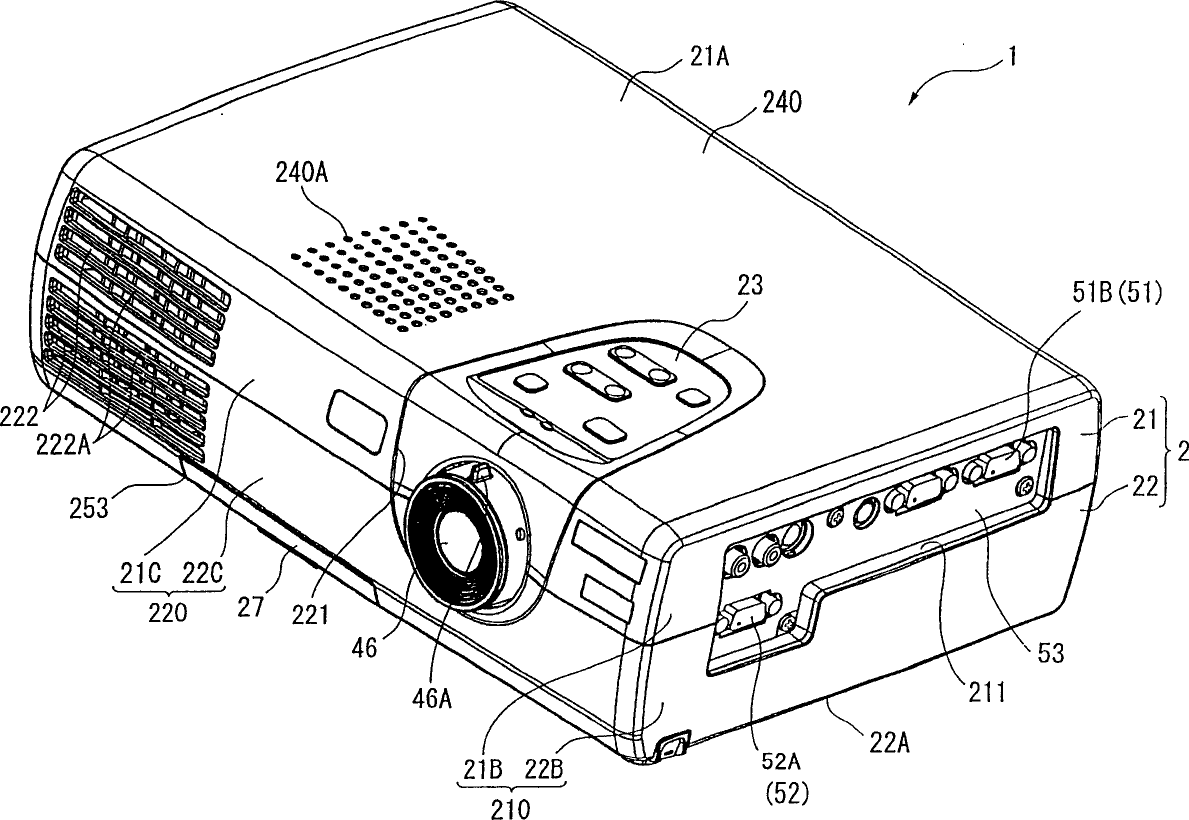
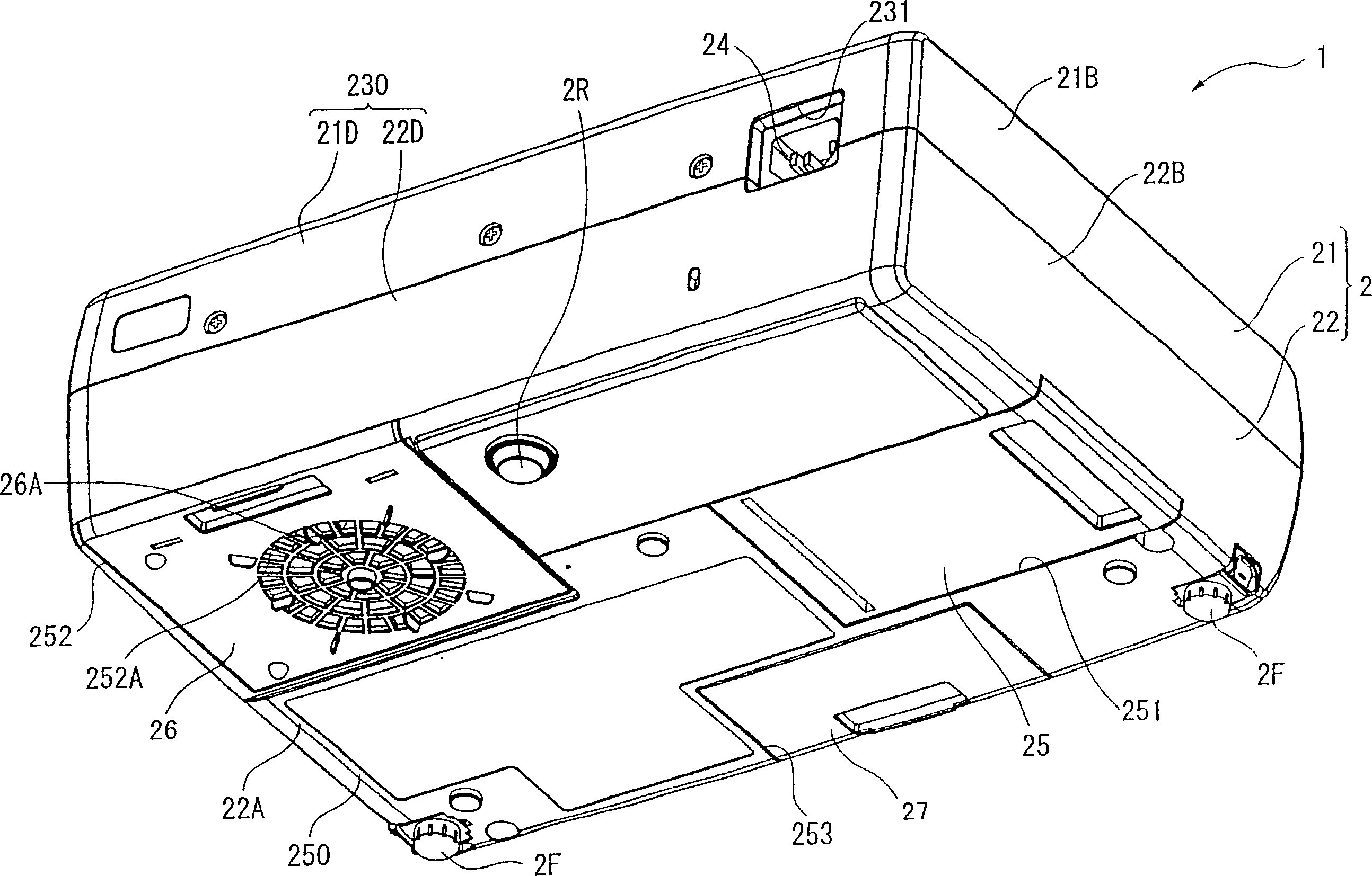
[0092] figure 1 is a perspective view of the projector 1 according to the present invention seen from the upper front side. figure 2 It is a perspective view of the projector 1 seen from the lower rear side.

[0093] Such as figure 1 or figure 2 As shown, the projector 1 includes a substantially rectangular parallelepiped outer casing 2 formed by injection molding. The outer cabinet 2 is a casing made of synthetic resin that accommodates the main body of the projector 1 , and includes an upper cabinet 21 and a lower cabinet 22 . These casings 21, 22 are mutually detachable.

[0094] Upper casing 21, such as figure 1 , 2 As shown, an upper portion 21A, a side portion 21B, a front portion 21C, and a rear portion 21D respectively constituting the upper face, the side face, the ...


PUM


Abstract

A projection lens (46) has a lens barrel (100) in which group lenses (110) are sequentially disposed and an optical path is set, the lens barrel (100) having position-adjusting holes (122A) on a position orthogonal to an optical axis of a third group lens (113) and being orthogonal with each other. The projection lens manufacturing apparatus has a projection lens holding mechanism (550) for holding the projection lens (46) at the lens-adjusting position; an image light irradiating mechanism (526) which introduces the test pattern image in accordance with a light beam irradiated by a light source (521) onto the projection lens (46); a lens position adjuster (570) which adjusts the position of the third group lens (113) along X-axis and Y-axis while detecting the image light irradiated through the projection lens (46); and a bonding mechanism (580) for bonding the adjusted third group lens (113).

Description

technical field [0001] The present invention relates to a projection lens manufacturing device, a projection lens manufacturing method, a projection lens manufactured by the projection lens manufacturing method, and a projector equipped with such a projection lens. Background technique [0002] In the prior art, a projector including a plurality of liquid crystal panels for modulating light of various colors for each color of light according to image information is used, and the light modulated by each liquid crystal panel is used. A cross dichroic prism for synthesizing light of each color, and a projection lens for enlarging and projecting the light beams synthesized by the prism to form a projected image. [0003] As a projection lens used in such a projector, in order to suppress the reduction in resolution and the occurrence of aberrations such as distortion aberration and chromatic aberration in projected images, a combination of a plurality of lenses including a conve...

Claims


Application Information

Patent Timeline
Patent Type & Authority Applications(China)
IPC IPC(8): G02B7/02G02B7/08G02B27/62
CPCG02B27/62G02B7/025G02B7/08
Inventor 藤泽尚平大久保弘达梅村俊次
Owner SEIKO EPSON CORP
Why Eureka
Try Eureka