

Electronic pipette
- Summary
- Abstract
- Description
- Claims
- Application Information
AI Technical Summary
Benefits of technology
Problems solved by technology
Method used
Image

Examples
Embodiment Construction
[0037] While this invention may be embodied in many different forms, there are described in detail herein a specific preferred embodiment of the invention. This description is an exemplification of the principles of the invention and is not intended to limit the invention to the particular embodiment illustrated
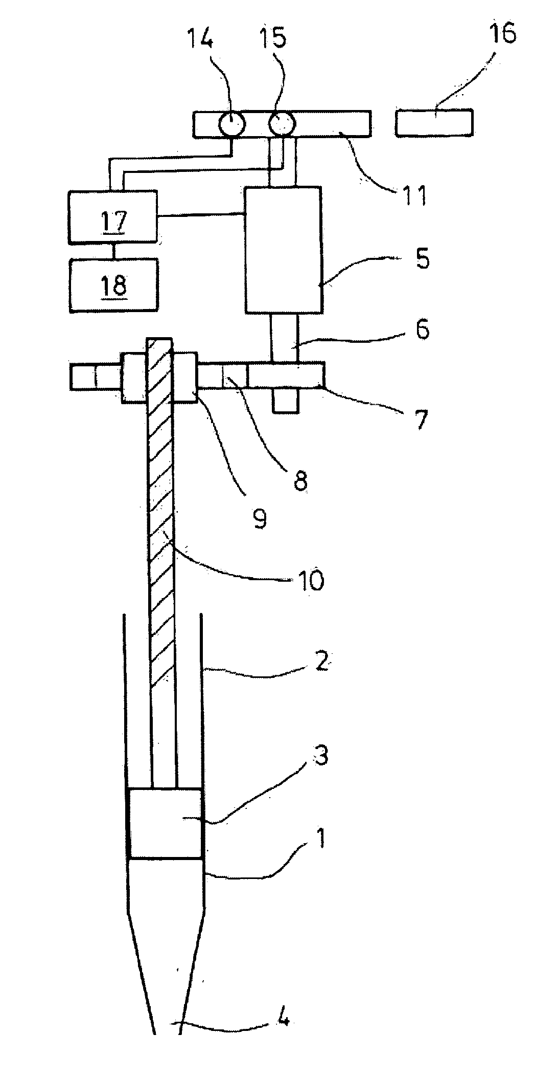
[0038] According to FIG. 1 an electronic pipette has a displacement device 1, which comprises a cylinder 2 with a piston 3 longitudinally displaceable therein. Releaseably (air cushion pipette) or individually (direct displacement pipette) attached to the cylinder 2 is a tip 4 which is a pipette tip or a syringe tip.
[0039] Moreover, the pipette comprises an electric drive motor 5, which comprises a drive shaft 6. The drive motor is a DC motor.
[0040] On a portion of the drive shaft 6 a small pinion 7 is positioned which meshes with a large pinion 8 which is rotationally fixedly attached to a spindle nut 9.
[0041] The spindle nut 9 is screwed onto a threaded spindle 10. The ...
PUM
 Abstract
Description
Claims
Application Information