Rotor having structural optimization

a technology of rotors and structural features, applied in the direction of dynamo-electric machines, magnetic circuit rotating parts, magnetic circuit shape/form/construction, etc., can solve the problems of affecting the magnetic properties of the rotor body, structural features used to maintain the positioning of flux barriers experience focused stresses, etc., to reduce space, strengthen magnetic interactions, and reduce the thickness or elimination of non-magnetic components

Inactive Publication Date: 2020-06-18
GM GLOBAL TECH OPERATIONS LLC
View PDF6 Cites 5 Cited by
  • Summary
  • Abstract
  • Description
  • Claims
  • Application Information

AI Technical Summary

Benefits of technology

[0003]Rotor bodies according to aspects of the present disclosure provide a number of benefits. For example, rotor bodies as disclosed herein optimize performance of the motor-generator though, for example, (1) strengthened magnetic interactions between the ferromagnetic components of the rotor body and electromagnetic components of the stator body by reducing space between a periphery of rotor body and inner surface of the stator, (2) reducing thickness of or eliminating non-magnetic components disposed between magnetic components of the rotor body and magnetic components of the stator, such as sleeves or wraps, and / or (3) reducing thickness of or eliminating flux-leaking components of the rotor body disposed proximate the stator body. Further, rotor bodies in accordance with the present disclosure provide for an increased number of flux barriers within the same space while maintaining or increasing structural integrity of the rotor body. Moreover, efficiency and peak rotational speeds are optimized by the curable filler providing structural integrity to the rotor body and thereby maintaining structural integrity of the rotor body at high RPM. Beneficially, rotor bodies in accordance with the present disclosure further optimize structural integrity during revolution of the rotor body by reducing rotor weight.

Problems solved by technology

More particularly, structural features used to maintain the positioning of the flux barriers experience focused stresses and affect magnetic properties of the rotor body.

Method used


Image

  • Rotor having structural optimization
  • Rotor having structural optimization
  • Rotor having structural optimization

Examples


Embodiment Construction

[0033]This disclosure is susceptible of embodiment in many different forms. Representative embodiments of the disclosure are shown in the drawings and will herein be described in detail with the understanding that these embodiments are provided as an exemplification of the disclosed principles, not limitations of the broad aspects of the disclosure. To that extent, elements and limitations that are described, for example, in the Abstract, Introduction, Summary, and Detailed Description sections, but not explicitly set forth in the claims, should not be incorporated into the claims, singly or collectively, by implication, inference or otherwise.

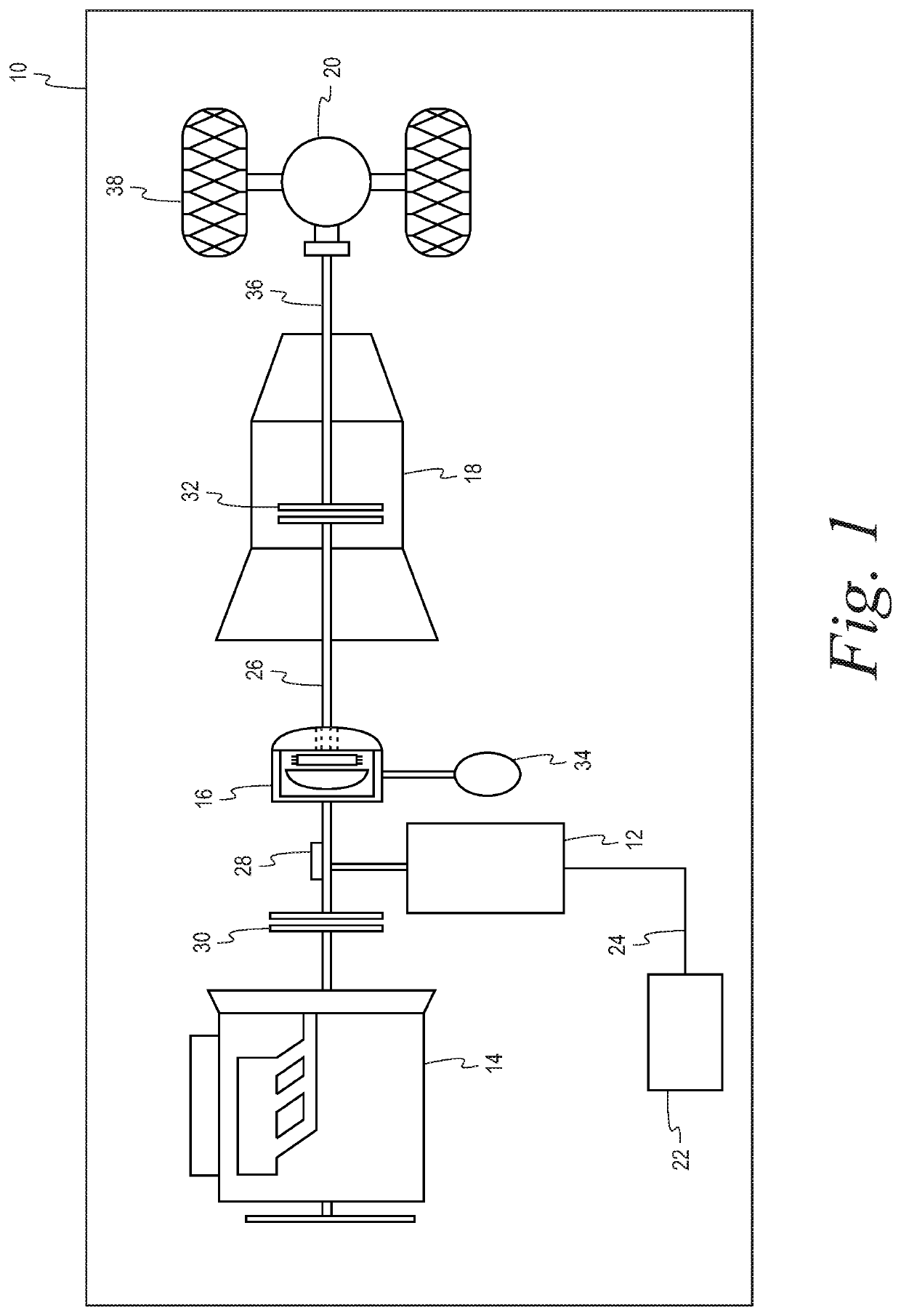
[0034]FIG. 1 is a schematic illustration of a vehicle 10 including a motor-generator 12, which is configured to propel the vehicle 10 alone and / or in concert with another power source, such as an engine 14. The vehicle 10 may be, for example, a hybrid electric vehicle, plug-in hybrid electric vehicle, range-extended hybrid electric vehicle, fu...


PUM


Abstract

Systems, methods, and devices including a rotor body including a curable material are described. The rotor body includes a plurality of ferromagnetic components arranged about an axis defining a circular periphery distal to the axis and a plurality of flux barriers. The plurality of ferromagnetic components define a plurality of channels arranged circumferentially about the axis. Each of the plurality of flux barriers includes a curable filler occupying a respective one of the plurality of channels. The curable filler is configured to maintain radial spacing of the plurality of ferromagnetic components and optimize mechanical stress across the rotor body.

Description

INTRODUCTION[0001]The present disclosure relates generally to electric machines. More specifically, aspects of this disclosure relate to rotors for electric motors.[0002]Rotary electric machines, such as motor-generator units, include a rotor body configured to rotate about an axis. During rotation, the rotor body experiences tensile stresses. The rotor body includes flux barriers therein, which affect tensile stresses through the body. More particularly, structural features used to maintain the positioning of the flux barriers experience focused stresses and affect magnetic properties of the rotor body.SUMMARY[0003]Rotor bodies according to aspects of the present disclosure provide a number of benefits. For example, rotor bodies as disclosed herein optimize performance of the motor-generator though, for example, (1) strengthened magnetic interactions between the ferromagnetic components of the rotor body and electromagnetic components of the stator body by reducing space between a ...

Claims


Application Information

Patent Timeline
Patent Type & Authority Applications(United States)
IPC IPC(8): H02K1/27H02K1/28H02K15/03
CPCH02K15/03H02K1/28H02K2201/03H02K1/2766H02K1/2706
Inventor FATEMI, ALIREZACOPPOLA, ANTHONY M.NEHL, THOMAS W.
Owner GM GLOBAL TECH OPERATIONS LLC
Why Eureka
Try Eureka