Fan and motor thereof

Active Publication Date: 2008-07-17
DELTA ELECTRONICS INC
View PDF6 Cites 27 Cited by
  • Summary
  • Abstract
  • Description
  • Claims
  • Application Information

AI Technical Summary

Benefits of technology

[0013]As mentioned above, the fan and the motor of the invention have the magnetic element disposed at the bottom of the bushing. Through the magnetic interaction between the magnetic element and one end of the shaft, the shaft can rotate stably without increasing the magnetic bias distance, which is the deviation between the central lines of the rotor and the stator. Compared with the related art, the invention can prevent erosions between components and noises, thus increasing the lifetime of the fan and

Problems solved by technology

The rotor further mechanically interferes with internal or external components of the motor.
This results in noises and component erosions.
This causes noises and component erosions, affecting the heat dissipation efficiency and lifetime of the fan 1.
However, the ma

Method used


Image

  • Fan and motor thereof
  • Fan and motor thereof
  • Fan and motor thereof

Examples


Embodiment Construction

[0018]The present invention will be apparent from the following detailed description, which proceeds with reference to the accompanying drawings, wherein the same references relate to the same elements.

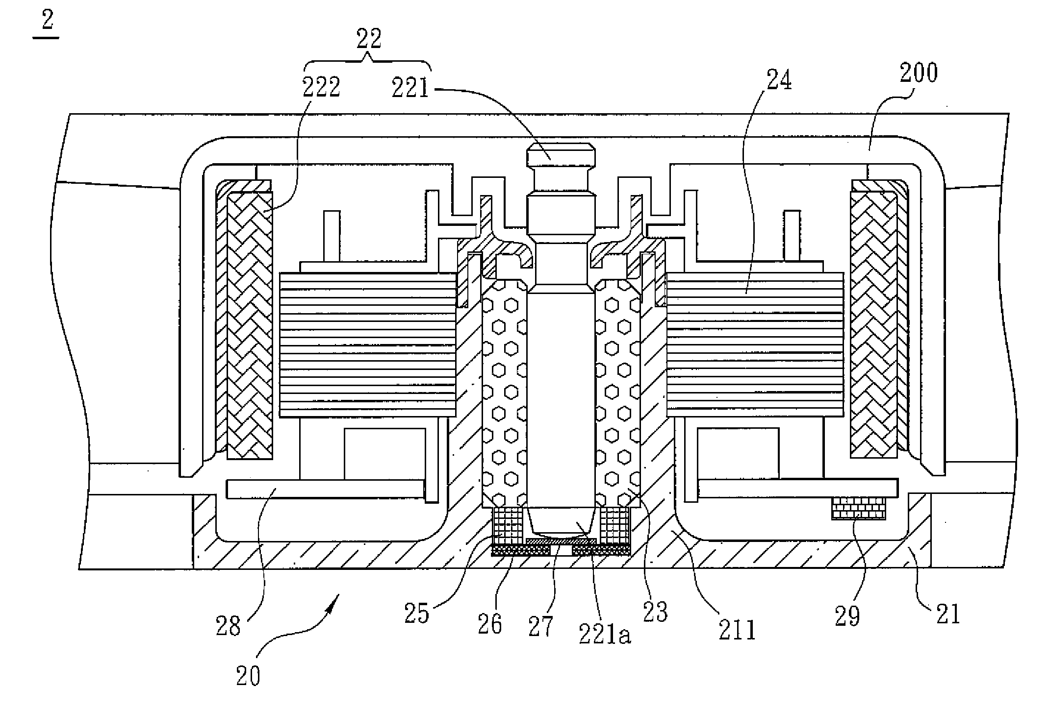
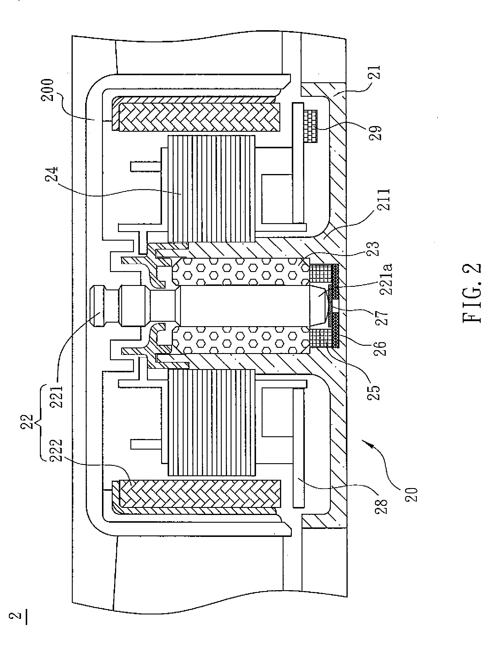
[0019]As shown in FIG. 2, the fan 2 according to an embodiment of the invention includes a motor 20 and an impeller 200. The motor 20 drives the impeller 200 to rotate. The motor 20 includes a base 21, a rotor 22, a bearing 23, a stator 24 and a magnetic element 25. The central portion of the base 21 is extended to form a bushing 211 for accommodating the bearing 23. The stator 24 is telescoped around the bushing 211. The rotor 22 has a shaft 221 and a magnetic ring 222. The magnetic ring 222 is disposed and corresponds to the stator 24. The stator 24 consists of a coil wound around several silicon steel sheets. The shaft 221 passes through the bearing 23. The magnetic element 25 is an annular structure disposed at the bottom of the bushing 211, surrounding one end 221a of the shaft 2...


PUM


Abstract

A fan includes a motor and an impeller. The motor drives the impeller to rotate and includes a base, a bearing, a stator, a rotor and a magnetic element. The central portion of the base is extended to form a bushing for accommodating the bearing therein. The stator telescopes around the bushing. The rotor is disposed corresponding to the stator and has a shaft passing through the bearing. The magnetic element is disposed at the bottom of the bushing and located adjacent to one end of the shaft.

Description

CROSS REFERENCE TO RELATED APPLICATIONS[0001]This Non-provisional application claims priority under 35 U.S.C. §119(a) on Patent Application No(s). 096101100 filed in Taiwan, Republic of China on Jan. 11, 2007, the entire contents of which are hereby incorporated by reference.BACKGROUND OF THE INVENTION[0002]1. Field of Invention[0003]The invention relates to a fan and a motor thereof and, in particular, to a fan and a motor that can maintain the stability and balance of their rotor.[0004]2. Related Art[0005]When a fan runs, the external force or airflow often acts on the rotor so that it shifts outward. The rotor vibrates up and down so that its balance position changes. The rotor further mechanically interferes with internal or external components of the motor. This results in noises and component erosions. The outward motion of the rotor increases the distance between the rotor and the magnetic sensing element, affecting the sensing effect of magnetic field on the magnetic sensing...

Claims


Application Information

Patent Timeline
IPC IPC(8): H02K7/14H02K7/08
CPCF04D29/057F04D29/058F04D25/062H02K7/09H02K7/14H02K7/085
Inventor LIN, YUNG-PINGYEH, DUNG-CHANGMA, XIAO-LINHU, YING-XIDUAN, YONG
Owner DELTA ELECTRONICS INC
Why Eureka
Try Eureka