Plunger for magnetic latching solenoid actuator

a solenoid actuator and magnet technology, applied in the field of magnets, can solve the problems of affecting the damage of the actuator, and the increase in the cost of producing magnetic products using such magnets, so as to improve the performance of the solenoid actuator and the stroke force. , the effect of improving the magnetic interaction

Active Publication Date: 2017-09-07
JOHNSON ELECTRIC SA
View PDF9 Cites 2 Cited by
  • Summary
  • Abstract
  • Description
  • Claims
  • Application Information

AI Technical Summary

Benefits of technology

[0026]Since contactor switches rely on powerful actuators to limit or minimise the amount of contact bounce, it follows that the improvements to the stroke force provided by the present actuator arrangement would be highly beneficial for such switches.
[0027]According to a third aspect of the invention, there is provided a method of improving the performance of a magnetic latching solenoid actuator, the method comprising the step of improving a magnetic interaction between a plunger and a magnet element of the magnetic latching solenoid actuator by modifying a cross-section of the plunger at or adjacent to the magnet element so as to be more square or rectangular so as to better match a shape of the magnet element.
[0028]Improving the magnetic interaction between a plunger and the latching magnets of a magnetic latching solenoid actuator beneficially improves the stroke force of the actuator, resulting in more effective and accurate motions of the plunger to be achieved.

Problems solved by technology

Given the scarcity of rare earth elements, the cost of producing magnetic products using such magnets is increasing.
The weaker magnetic field of a ferrite magnet when compared with a rare earth magnet does, however, pose problems for the construction of actuators.
This can have deleterious effects for applications where a strong and consistent stroke is required in order to have any specific effect.
Actuators for switching contactor arrangements are one such area in which the stroke force is critical, since a weaker stroke force can lead to electrical arcing between contacts and / or contact bounce, either of which can damage the switching contactor and cause faults over time.

Method used


Image

  • Plunger for magnetic latching solenoid actuator
  • Plunger for magnetic latching solenoid actuator
  • Plunger for magnetic latching solenoid actuator

Examples


Embodiment Construction

[0039]The technical solutions of the embodiments of the present invention will be clearly and completely described as follows with reference to the accompanying drawings. Apparently, the embodiments as described below are merely part of, rather than all, embodiments of the present invention. Based on the embodiments of the present disclosure, any other embodiment obtained by a person skilled in the art without paying any creative effort shall fall within the protection scope of the present invention.

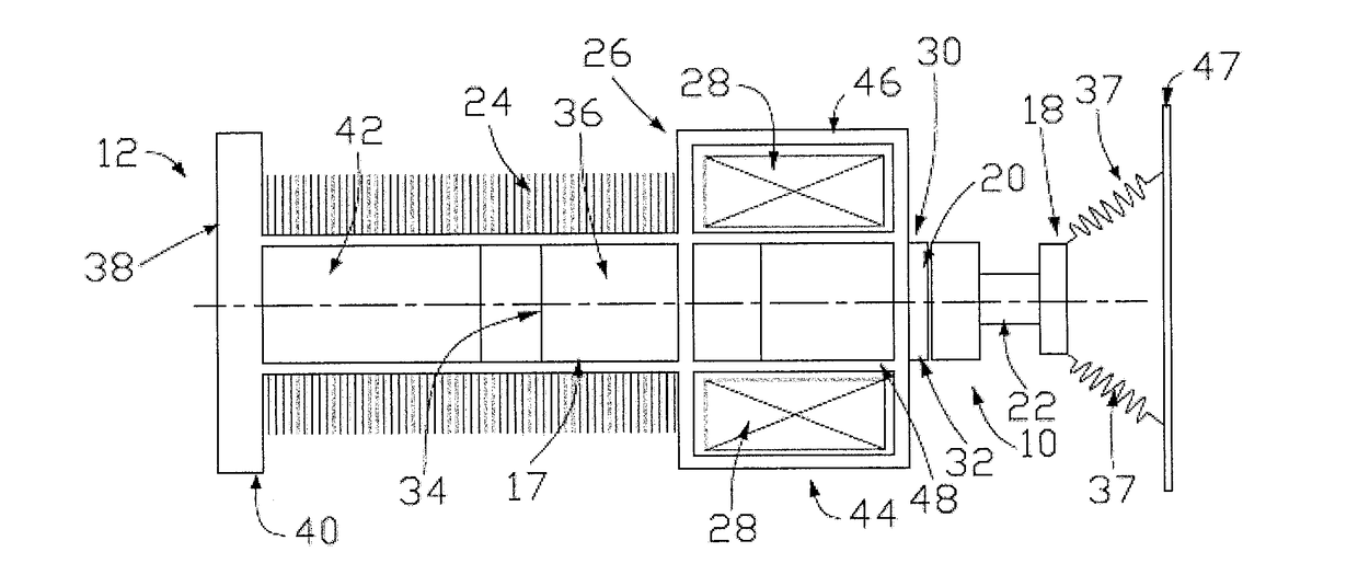
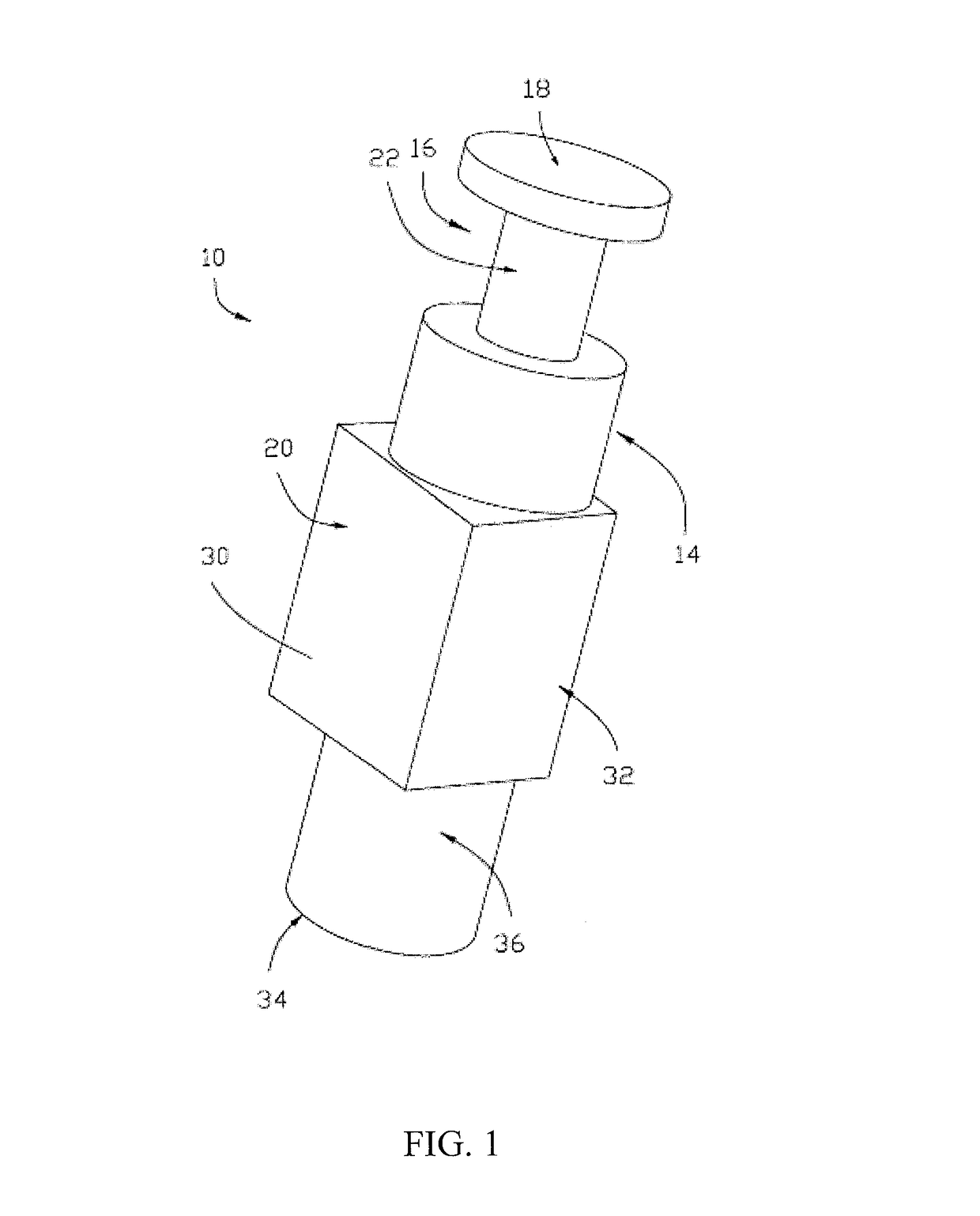
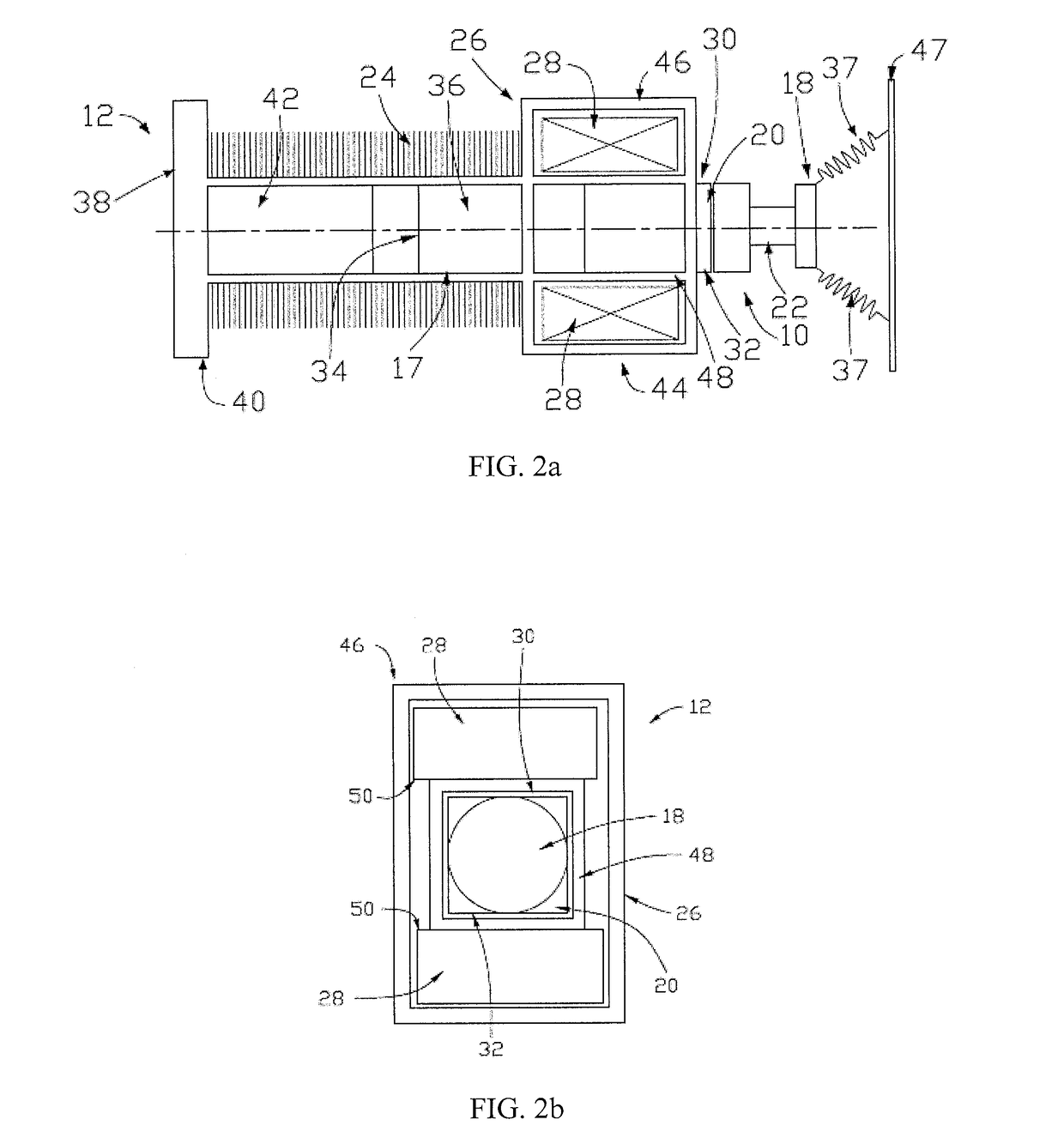
[0040]Referring firstly to FIG. 1, there is provided a plunger for a magnetic latching solenoid actuator, the plunger being indicated globally by 10. Such a plunger 10 provides an improved performance of a magnetic latching solenoid actuator, such as that indicated generally in FIGS. 2a to 3, and referenced generally as 12.

[0041]The plunger 10 comprises an elongate, preferably predominantly cylindrical, plunger body 14, which has at one end 16 a plunger head 18 which is capable of transf...


PUM

PropertyMeasurementUnit
cross-sectional areaaaaaaaaaaa
widthaaaaaaaaaa
magneticaaaaaaaaaa

Abstract

A plunger includes an elongate plunger body which is at least in part cylindrical and a plunger head at one end of the plunger body. The plunger body has a magnet-interface body portion which has a non-cylindrical cross-section perpendicular to a longitudinal axis of the plunger body. A magnetic latching solenoid actuator using such a plunger is also provided, as is a method of improving the performance of a magnetic latching solenoid actuator.

Description

CROSS REFERENCE TO RELATED APPLICATIONS[0001]This non-provisional patent application claims priority under 35 U.S.C. §119(a) from Patent Application No. 1603792.1 filed in Britain on 4 Mar., 2016.FIELD OF THE INVENTION[0002]The present invention relates to a plunger for use with a magnetic latching solenoid actuator, and in particular but not necessarily exclusively for switching contactor actuator arrangements. The invention further relates to a magnetic latching solenoid actuator, and also to improving the performance of a magnetic latching solenoid actuator.BACKGROUND OF THE INVENTION[0003]In order to increase the cost-effectiveness of production of solenoid actuators, in many cases, a magnet element of the actuator has utilised traditional ferrite magnets in lieu of the more powerful rare earth magnets. Given the scarcity of rare earth elements, the cost of producing magnetic products using such magnets is increasing.[0004]The weaker magnetic field of a ferrite magnet when compa...

Claims


Application Information

Patent Timeline
Patent Type & Authority Applications(United States)
IPC IPC(8): H01F7/16H01F7/121
CPCH01F7/121H01F7/1615H01H50/20H01H50/641H01F7/13
Inventor CONNELL, RICHARD ANTHONY
Owner JOHNSON ELECTRIC SA
Why Eureka
Try Eureka