High-efficiency wheel-motor utilizing molded magnetic flux channels with transverse-flux stator

a technology of transverse flux and motor, applied in the direction of electronic commutators, magnetic circuit shapes/forms/construction, stopping arrangements, etc., can solve the problems of reducing the maximum amount of torque produced, reducing the magnetic strength, and only blocking the eddy current in one plane, so as to reduce the hysteresis loss, improve torque and efficiency, and reduce interference

Inactive Publication Date: 2011-01-11
RITTENHOUSE NORMAN P
View PDF20 Cites 27 Cited by
  • Summary
  • Abstract
  • Description
  • Claims
  • Application Information

AI Technical Summary

Benefits of technology

[0016]A third objective of the invention is to provide methods, systems and devices for a high efficiency direct drive high torque motor using mated pole pieces accommodating a rotor permanent magnet using both sides of the rotor's permanent magnets to eliminate the need for a magnetic flux return path for adjacent magnets resulting in increasing magnetic performance per pound of permanent magnet material.
[0022]The present invention overcomes the problems with the prior art U.S. Pat. No. 7,492,074 patent issued Feb. 17, 2009 to the same inventor as the subject application, which is incorporated herein by reference, with the following improvements:1) Overall weight of motor / generator reduced by approximately greater than 50 percent.2) Size, weight, and cost of the permanent magnets by approximately greater than one-half.3) Mating molded magnetic flux-channel pole pieces have simplified, shortened magnetic path.4) An outer steel shell replaced with other inert materials such as fiberglass or carbon fiber to reduce the overall weight of the motor.5) Simplified building block construction.6) Improved driving electronics
[0026]The electronics can also include an LRC filter connected between the semiconductor switches and the one of the STAR, DELTA, OR WYE electrical circuits to remove switching frequency noise to reduce interference to the magnetization response of the molded magnetic flux channels pole pieces to reducing hysteresis loss and improve torque and efficiency and can include a feedback circuit for obtaining a current feedback waveform from the output of the LRC filters, wherein the processing unit compares the current feedback signal with a stored optimal current waveform to generate a corrected applied voltage and current waveform to driving the transverse windings of the motor during operation. The controller feedback circuit can include plural cascaded Hall effect sensors located near the path of the rotor permanent magnets to generate a stair step sine wave to conveys information on rotor speed, direction, and timing to the processing for generating an output waveform for driving the motor.
[0027]The controller can include a waveform lookup table stored in memory coupled with the processing unit, the waveform lookup table containing digital representations of optimal current and voltage waveforms for best motor performance at various speeds, power loadings, acceleration and deceleration rates, wherein the processing unit compares the feedback signal with data in the waveform lookup table to adjust the output of the drive electronics and / or an over-running fly-forward diode in series with each semiconductor switch to allow higher speed motor operation wherein the reverse EMF voltage of the stator can exceed the maximum power supply voltage available.

Problems solved by technology

However, even with thinner laminations, the eddy currents are only blocked in one plane.
Although the silicon reduces some remaining eddy current losses (by reducing the current conductivity), the addition of silicon actually worsens the magnetic conductivity.
This reduction of magnetic strength reduces the maximum amount of torque produced, and also reduces electrical efficiency.
The close coupled proximity results in “Armature Effect” which reduces efficiency at higher speeds.
At higher speeds, the inductive and reactive losses limit top speed and efficiency at high speed.
However, it does not involve Transverse Flux and does not use molded material for the stator.
Prior art transverse Flux motors have historically been too costly to construct, and have rarely been used.
The differences between the “claw pole” and the parallel pole motor is that claw pole motors have been around since the 1930's and have fatal disadvantages including that they are extremely inefficient—typical values of efficiency are 45-65%; they are limited in torque; eddy currents are very high and fringing losses are very high.
That trapezoidal shape of poles however, further limits torque.
The Rittenhouse '074 patent also overcomes prior problems associated with boosting magnetic flux, which increases inductance and resistance and at higher speeds; the inductive losses limit top speed and efficiency at high speed.
However, performance and cost of Neodymium-iron-boron permanent magnets have increased since the development and filing of the Rittenhouse '074 patent.

Method used


Image

  • High-efficiency wheel-motor utilizing molded magnetic flux channels with transverse-flux stator
  • High-efficiency wheel-motor utilizing molded magnetic flux channels with transverse-flux stator
  • High-efficiency wheel-motor utilizing molded magnetic flux channels with transverse-flux stator

Examples


Embodiment Construction

[0052]Before explaining the disclosed embodiments of the present invention in detail it is to be understood that the invention is not limited in its application to the details of the particular arrangements shown since the invention is capable of other embodiments. Also, the terminology used herein is for the purpose of description and not of limitation.

[0053]The following is a list of the reference numbers used in the drawings and the detailed specification to identify components:

[0054]

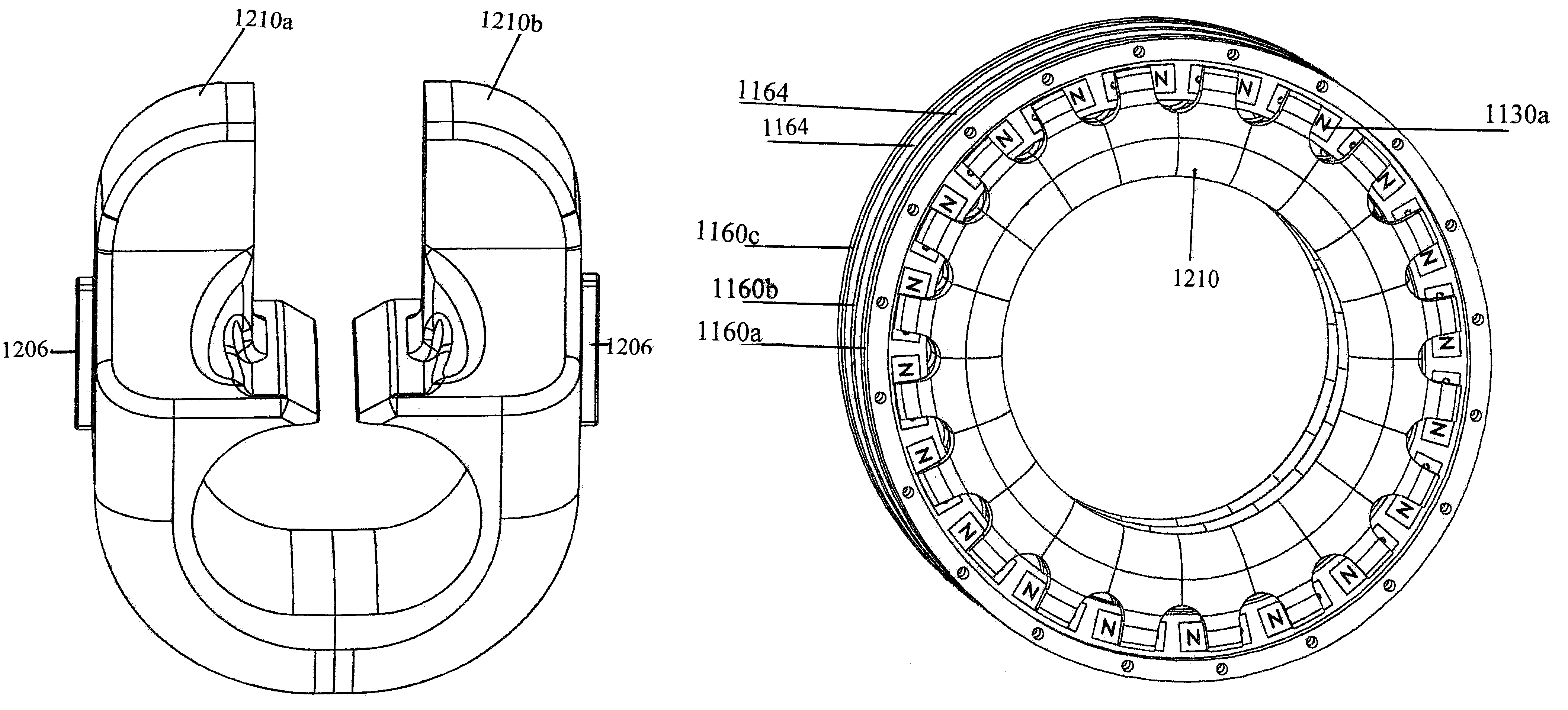
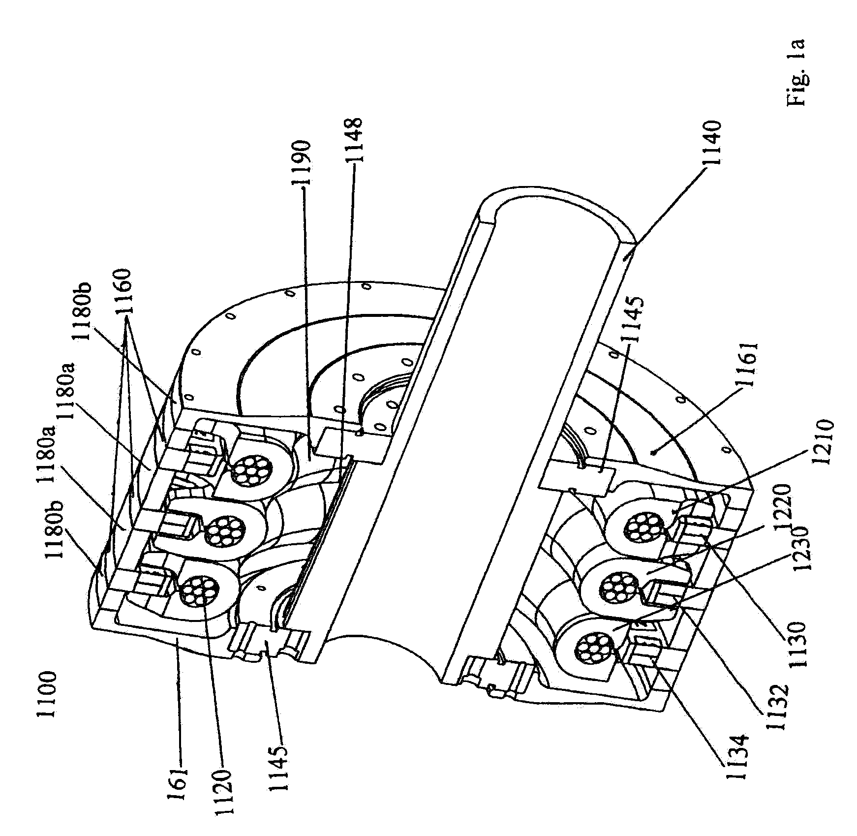
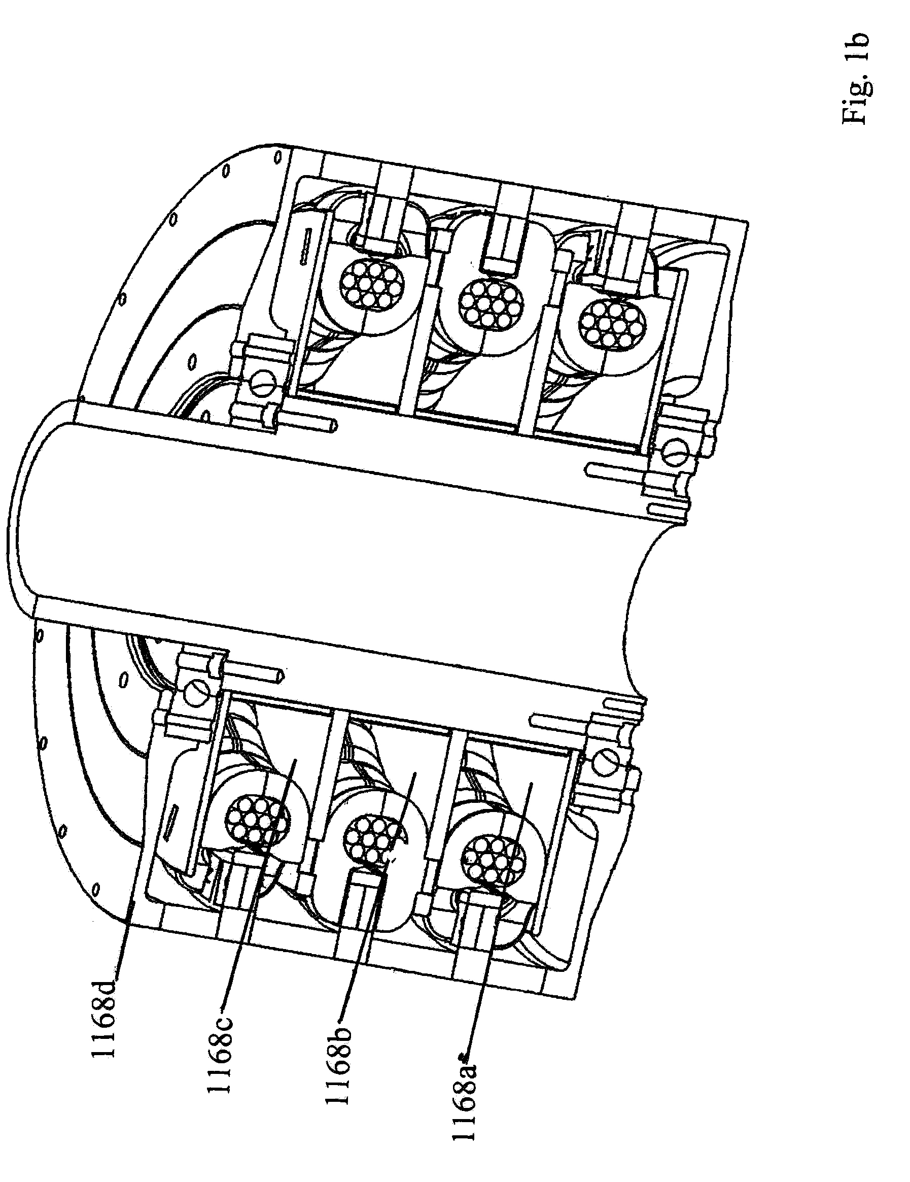
1100motor1120transverse winding1125channel1130permanent magnets1130apermanent magnets, phase A1130bpermanent magnets, phase B1130cpermanent magnets, phase C1135aair gap1135bair gap1140mounting shaft1145bearing1148splined surface 150Magnetic Flux Channels1160rotating disc1160arotating disc, phase A1160brotating disc, phase B1160crotating disc, phase C1161rotating end plate 162mounting shaft hole1164spacer 166hub1168aalignment plate, phase A1168balignment plate, phase B1168calignment plate, phase C1170...


PUM


Abstract

A motor including an outside rotor having a rotor disc with plural magnets alternating polarities flush mounted in the disc, an inside stator assembly with a ring of pole pieces forming a channel to house a transversely wound stator windings, and a controller coupled with feedback electronics for monitoring a timing, speed and direction and coupling a signal to a processing unit for adjusting the drive electronics driving the phase windings. A u-shaped gap above the channel to receive the rotor disc and focus the captured magnetic flux in the pole pieces toward the magnets. In an embodiment the molded magnetic flux channel pole pieces of the inside stator are sets of molded magnetic flux channel pole pieces, each set forming a channel and corresponding to one phase of the motor; and a section of each one of the transverse windings passing through one channel, the remaining section folding back outside the set in close proximity to the outer base of the set of molded magnetic flux channel pole pieces.

Description

[0001]This application is a continuation-in-part of U.S. application Ser. No. 12 / 371,823 filed on Feb. 16, 2009, which is a divisional application of U.S. application Ser. No. 11 / 731,427 filed on Mar. 30, 2007, now U.S. Pat. No. 7,492,074.FIELD OF THE INVENTION[0002]This invention relates to motors and, in particular, to methods, systems and apparatus for a high efficiency direct drive high torque parallel pole motor utilizing mated molded magnetic flux channel parallel pole pieces with transverse flux stator windings.BACKGROUND AND PRIOR ART[0003]Approximately 93% of motors constructed use iron cores, or variations thereof, to concentrate magnetic flux and boost torque. “Coreless” motors are suited for very high RPM's with low torque and iron core motors usually utilize insulated steel laminations in their stators which reduce heat losses from eddy currents. However, even with thinner laminations, the eddy currents are only blocked in one plane. So to further reduce eddy current lo...

Claims


Application Information

Patent Timeline
Patent Type & Authority Patents(United States)
IPC IPC(8): H02K1/02
CPCH02K1/2786H02K21/125H02K21/227H02P6/16H02P6/20H02P6/24H02P23/03H02P25/18H02K2201/12Y02E10/725Y02E10/72H02K1/2791
Inventor RITTENHOUSE, NORMAN P.
Owner RITTENHOUSE NORMAN P
Why Eureka
Try Eureka