Photothermal transducing spectroscopic analyzer

a spectroscopic analyzer and photothermal technology, applied in the direction of spectrometry/spectrophotometry/monochromators, instruments, optical radiation measurement, etc., can solve the problems of inability to adapt to the photoinduced fluorescence method, inability to achieve absorption photometry, and large background, etc., to achieve high-precision adjustment of a location

Inactive Publication Date: 2006-05-02
ASAHI KASEI KK
View PDF50 Cites 9 Cited by
  • Summary
  • Abstract
  • Description
  • Claims
  • Application Information

AI Technical Summary

Benefits of technology

[0077]In such a construction, since it is possible to quantify the positional relation of the focal points of excitation light and probe light, and a sample cell by using the light reflected from the sample cell, it becomes possible to perform the highly precise adjustment of a location which is needed when a condenser lens with large numerical aperture is used. In addition, since the above-described positional relation can be quantified, it is possible to automate the adjustment of a location of a sample cell after installing the sample cell in the photothermal spectroscopic analyzer.

Problems solved by technology

However, the photoinduced fluorescence method has a problem that background becomes large by fluorescence from other objects than a measuring object in practical samples with many impurities since the light with wavelength near an ultraviolet ray is generally used in many cases as a light source to excite the measuring object.
In addition, since a measuring object is limited to fluorescent material, it is not general as a detection method in clinical inspection such as an analysis of blood components.
Furthermore, although there is an advantage that the chemiluminescence method does not need a light source for excitation, it has not versatility similarly to the photoinduced fluorescence method.
However, in μ-TAS, since the optical path length becomes 1 / 10 to 1 / 100 as described above, the absorption photometry has a problem that sensitivity is low when it is applied to μ-TAS although it is a common and highly versatile detection method.
Although the single beam method is characterized in simple structure and easy optical adjustment, it becomes difficult to set the optimal optical configuration for each of excitation and detection since one laser performs both the excitation and the detection of a thermal lens, and sensitivity is low in comparison with the double beam method.
However, presently, when an apparatus generating the above-described laser beams is actually used, the apparatus is large-sized, large-scale cooling means such as water cooling means is needed at the time of a high-power output, and the apparatus becomes very expensive.
However, each of these three examples uses a helium neon laser, which is comparatively large-sized and expensive, as probe light, and hence, this is not an apparatus composed of only semiconductor lasers.
However, the above-described conventional technology has the following problems when realizing the photothermal spectroscopic analyzer which is equipped with high sensitivity, high accuracy, maintenance-free performance, short start-up time, and high reliability and operability in addition to the natural requirements for performing a POC analysis etc., that is, small dimensions for portable use and inexpensiveness.
However, since its sensitivity is low in comparison with the double beam method, its sensitivity is insufficient in many cases as a method of using this in the case, where high accuracy is required in data, such as medical diagnosis or an environmental analysis.
Next, in the conventional double beam method, only an excitation light source is composed of a semiconductor laser, and a helium neon laser that is large-sized and expensive is still used as a probe light source.
However, since the size of the helium neon laser which is a light source is usually 5 cm dia.×20 cm long, the apparatus become large-sized when this is added (D. Rojas et al., Rev. Sci. Instrum., Vol. 63, 2989–2993, 1992).
In addition, since a large-sized laser such as a helium neon laser is used, a light source and an optical system cannot be integrated and the light source and optical system are separately fixed on an optical bench, and hence, carrying is impossible.
Furthermore, a gas laser also has troubles such as necessity of a high voltage power supply.
Thus, since long distance is necessary for leading the probe light, which is given the thermal lens effect in the sample, to a pinhole, the miniaturization of the whole optical system is disturbed due to the restriction of such distance from the sample to the device.
If this distance is shortened without design, it is expected that it leads to sensitivity deterioration.
However, there is no report of affirming that the sensitivity of this method is superior to that of the pinhole method (Japanese Patent Laid-Open No. 4-369467 applied by YOKOGAWA ELECTRIC CORP.).
However, since the optimal degree of focusing or the optimal focal point of probe light depend on a plurality of other parameters and it is not possible to theoretically analyze all of those parameters systematically, there is no report of the theoretical analysis of the optimum values at the time of raise the degree of focusing, up to now.
Since a focal length becomes short to several cm when the numerical aperture is increased, it is not possible to make the excitation light and probe light be coaxial due to a spatial limitation in the case that the degree of focusing and the focal point of the probe light are adjusted by using separate condenser lenses for the excitation light and the probe light like a conventional way.
However, there is no report about an adjusting method of a focal point of probe light at the time of sharing a condenser lens.
Up to now, since the positional relation of a focal point and a sample cell is visually adjusted by using a microscope, not only a visual alignment error arises, but also an alignment error by a measuring operator is included.
In addition, it is impossible to automatically adjust an above-described positional relation with a machine in such visual method.
Furthermore, an apparatus becomes large by using a microscope.
In addition, since not only about 10 minutes of time was necessary until being stabilized after switching on a power supply but also mechanical modulation means such as a chopper was required for a gas laser at the time of modulating an output, it was not so easy to perform miniaturization and cost reduction.

Method used


Image

  • Photothermal transducing spectroscopic analyzer
  • Photothermal transducing spectroscopic analyzer
  • Photothermal transducing spectroscopic analyzer

Examples


example 1

[0159]An example where optics are separately fixed on an optical bench, a microscope is used, and both the light sources of excitation light and probe light are made of semiconductor laser beam-emitting apparatuses will be described in detail.

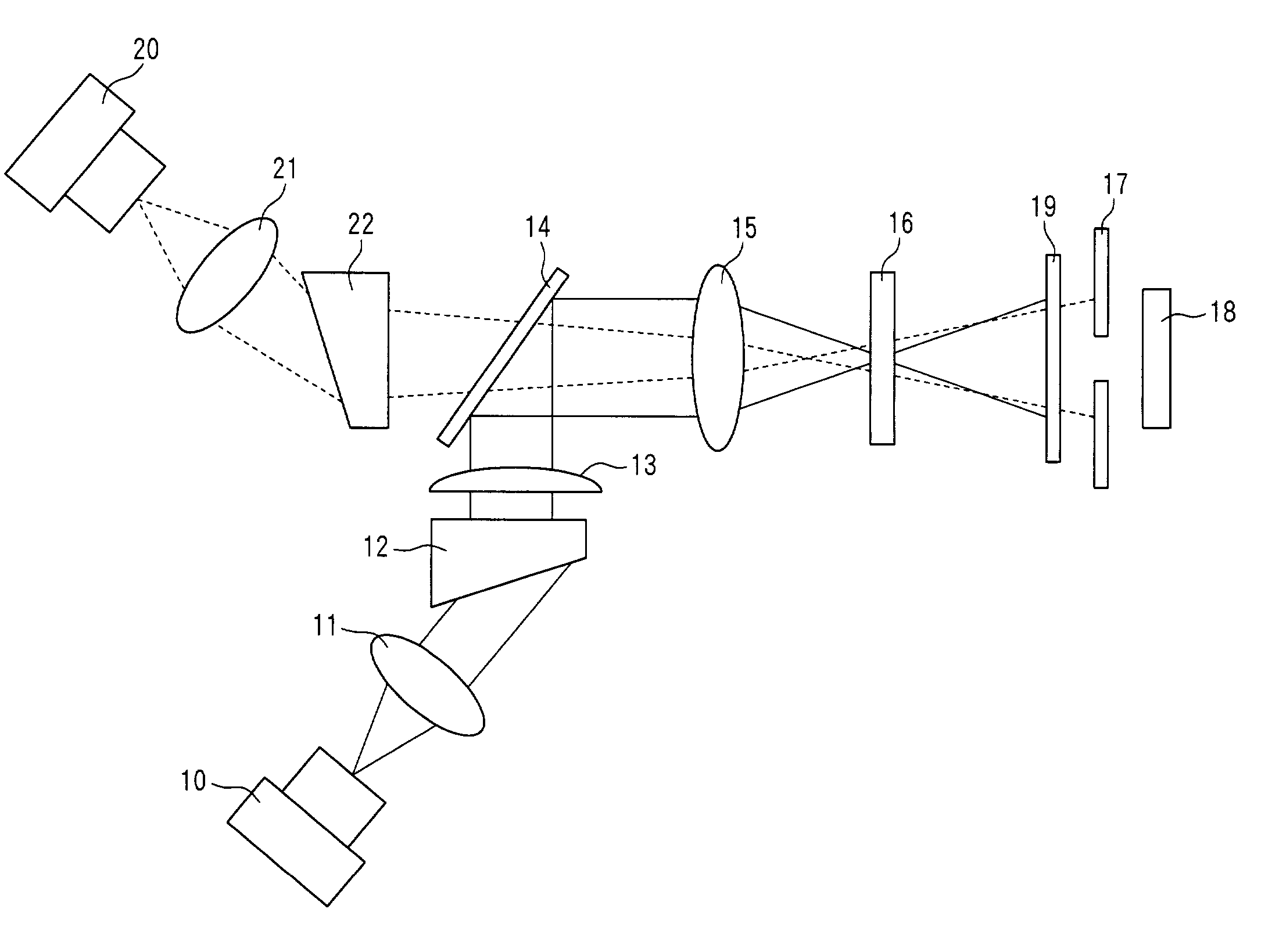
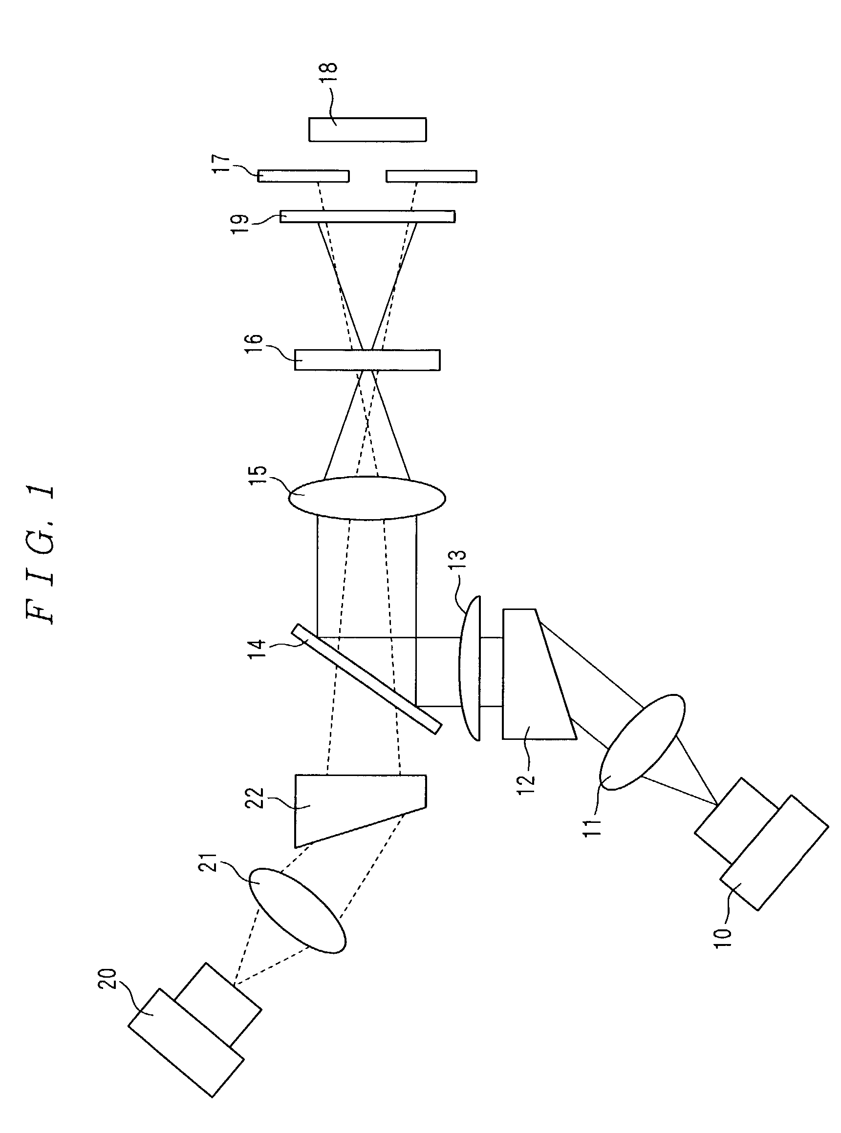
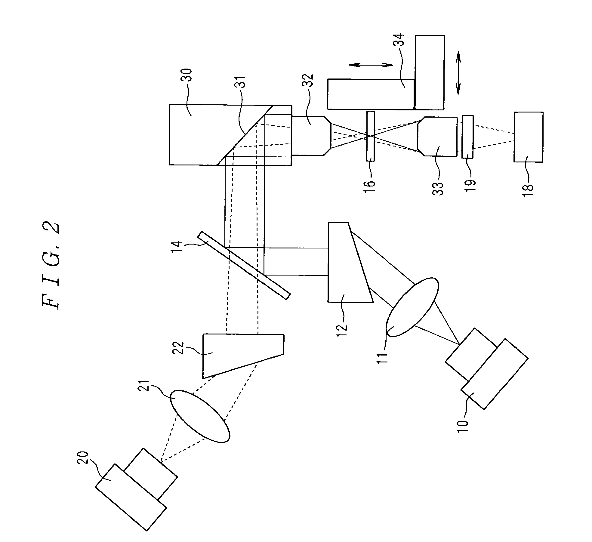
[0160]FIG. 2 is a structural diagram explaining a construction of a photothermal spectroscopic analyzer used in this example. In addition, since the construction of a photothermal spectroscopic analyzer in FIG. 2 is almost the same as the construction of the photothermal spectroscopic analyzer in FIG. 1, only different portions will be described and the explanation of the same portions will be omitted. In addition, in FIG. 2, the same symbols in FIG. 1 are assigned to the portions identical or equivalent to those in FIG. 1.

[0161]A semiconductor laser beam-emitting apparatus with the wavelength of 635 nm and a rated output of 20 mW (DL-4038-025 made by SANYO Electric Co., Ltd.) was used for a light source 10 of excitation light. A constant curre...

example 2

[0187]An example of which miniaturizing and integrating a portion from a light source to detection means will be described in detail with referring to FIG. 5. In addition, in FIG. 5, the same symbols in FIG. 1 are assigned to the portions identical or equivalent to those in FIG. 1. In addition, in this example, although several kinds of our own optics are used, it is natural to use commercial optics so long as they have the same characteristics.

[0188]A semiconductor laser beam-emitting apparatus with the wavelength of 635 nm and a rated output of 30 mW (LTO51PS, made by Sharp Corporation) was used for a light source 10 of excitation light. In addition, a semiconductor laser beam-emitting apparatus with the wavelength of 780 nm and a rated output of 50 mW (ML60114R, made by Mitsubishi Electric Corporation) was used for the light source 20 of probe light. These semiconductor lasers were made to enable output control and current control by commercial LD drivers (ALP-6323CA, made by Asa...


PUM

PropertyMeasurementUnit
diameteraaaaaaaaaa
diameteraaaaaaaaaa
wavelengthaaaaaaaaaa

Abstract

In a photothermal spectroscopic analyzer in which a probe light is made to fall on a thermal lens produced in a sample by an input of an excitation light and the sample is analyzed in accordance with a change of the probe light which is caused by the thermal lens, a light source of excitation light is composed of semiconductor laser light emitting means, and a light source of the probe light is composed of another semiconductor laser light emitting means, and furthermore a condenser lens for focusing the excitation light upon the sample and a condenser lens for focusing the probe light upon the thermal lens are configured by a common condenser lens. Such a photothermal spectroscopic analyzer according to the present invention satisfies all the requirements of small size, low manufacturing cost, high sensitivity, high precision, maintenance free performance, short start-up time, and automatic measurement for such a device as to perform POC analysis.

Description

TECHNICAL FIELD[0001]The present invention relates to a small and inexpensive photothermal spectroscopic analyzer which analyzes a microvolume sample in high sensitivity by using a semiconductor laser.BACKGROUND ART[0002]The importance has been noted of carrying out analysis and measurements right at the site or in the vicinity of the site where analysis and measurements are required (hereinafter referred to as “POC (point of care) analysis etc.”), such as analysis for bedside diagnosis which carry out measurements necessary for a medical diagnosis at the patient's side (POC analysis), analysis of toxic substances in rivers or wastes carried out at the sites, that is, on rivers, waste disposal centers and the like, and tests for contamination carried out at the site of cooking foods, harvesting crops, or importing foods. Then, importance has been attached to the development of detection methods and detection apparatus which are applied to such POC analysis etc. in recent years.[0003...

Claims


Application Information

Patent Timeline
Patent Type & Authority Patents(United States)
IPC IPC(8): G01N21/63G01J1/04G01J5/08G01N21/71G01N21/17
CPCG01N21/171G01N2021/1712
Inventor MAWATARI, KAZUMA
Owner ASAHI KASEI KK
Why Eureka
Try Eureka