Status monitoring method for spark gap trigger circuit

A spark gap and trigger circuit technology, which is applied in the direction of measuring electricity, measuring devices, and measuring electrical variables, etc., can solve the problems of spark gap circuit fault analysis, on-site debugging and maintenance difficulties, weak device status monitoring function, and the inability to realize spark gap trigger circuit Condition monitoring and other issues, to facilitate on-site debugging and maintenance, and to solve the effect of fault location

Active Publication Date: 2012-07-25
CHINA EPRI SCIENCE & TECHNOLOGY CO LTD +2
View PDF4 Cites 4 Cited by
  • Summary
  • Abstract
  • Description
  • Claims
  • Application Information

AI Technical Summary

Problems solved by technology

However, the existing spark gap triggering device focuses on the triggering function, and the state monitoring function of the device is very weak, and it is impossible to realize the state monitoring of the spark gap triggering circuit
[0005] The existing spark gap triggering device cannot reliably monitor the state of the gap triggering circuit, and send the status information to the control and protection device in real time, which cannot solve the problem of fault location of the spark gap triggering circuit, making fault analysis, on-site debugging and difficult to maintain

Method used


Image

  • Status monitoring method for spark gap trigger circuit
  • Status monitoring method for spark gap trigger circuit
  • Status monitoring method for spark gap trigger circuit

Examples


Embodiment Construction

[0031] Embodiments of the present invention will be further described below in conjunction with the accompanying drawings.

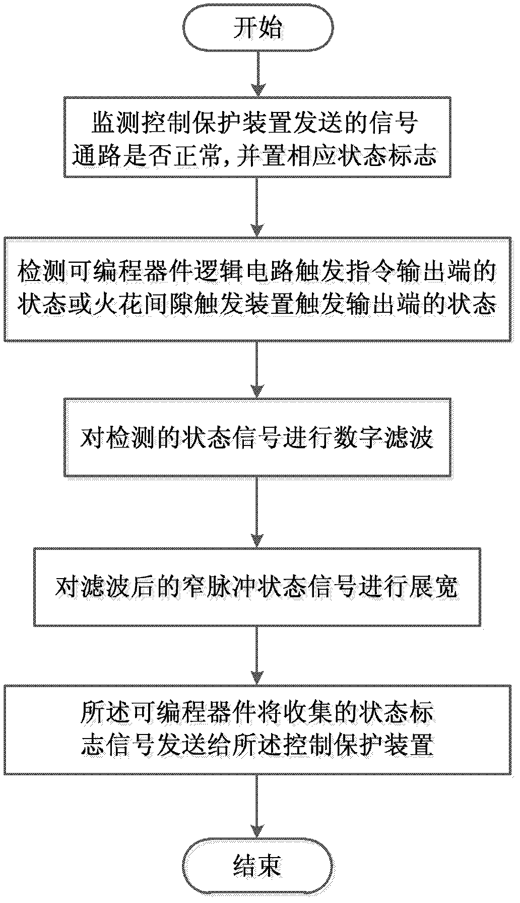
[0032] Such as figure 1 Shown, a kind of spark gap trigger circuit state monitoring method, described method comprises the following steps:

[0033] (1) Monitor whether the signal path sent by the control protection device is normal;

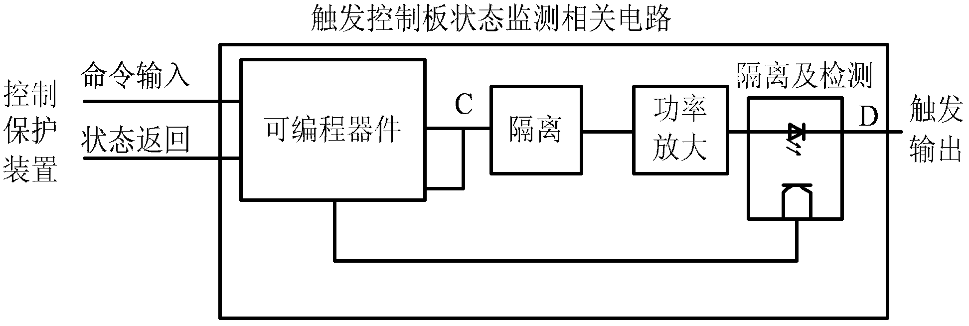
[0034] (2) Detect the state of the trigger command output end of the logic circuit of the programmable device or the state of the trigger output end of the spark gap trigger device;

[0035] (3) Carry out digital filtering to the detected state signal;

[0036] (4) widening the filtered narrow pulse state signal;

[0037] (5) The programmable device sends the collected status flag signal to the control and protection device.

[0038] Described step (1) comprises the following steps:

[0039] (1-1) The control protection device sends pulse signals of two different frequencies to the trigger control board of the spark g...


PUM


Abstract

The invention provides a status monitoring method for a spark gap trigger circuit, which includes the steps: monitoring normality of a path of signal transmitted by a control protector; detecting the status of a trigger instruction output end of a programmable device logic circuit or the status of a trigger output end of a spark gap trigger device; subjecting the detected status signals to digital filtering; broadening narrow-pulse status signals obtained by filtering; and allowing a programmable device to transmit collected status marking signals to the control protector. By the method, the status of the gap trigger circuit can be determined timely and accurately; transient trigger pulse is detected at the trigger output end of the spark gap trigger device; transient status information is reliably transmitted to the control protector in milliseconds; and accordingly the problem of locating failure of the spark gap trigger circuit is well solved, and field debugging and maintenance of the spark gap circuit are facilitated greatly.

Description

technical field [0001] The invention belongs to the technical field of power systems and power electronics, and in particular relates to a spark gap trigger circuit state monitoring method. Background technique [0002] At present, suppliers of series compensation devices include ABB, GE, Siemens and China Electric Power Research Institute. These four units can all produce spark gaps, but the principles of triggering ignition are different, and the principles of corresponding spark gap triggering devices are also different. [0003] The control and protection device of the series capacitor consists of metal oxide voltage limiter MOV (Metal Oxide Voltage Limiter), forced trigger spark gap, damping circuit and bypass circuit breaker. Metal Oxide Voltage Limiter MOVs limit the voltage level across series capacitors during system faults; forced spark gaps are compensated by fixed series capacitors when Metal Oxide Voltage Limiter MOVs absorb too much energy or in cases where fa...

Claims


Application Information

Patent Timeline
Patent Type & Authority Applications(China)
IPC IPC(8): G01R31/00
Inventor 詹雄刘慧文戴朝波燕翚崔虎宝李甲飞
Owner CHINA EPRI SCIENCE & TECHNOLOGY CO LTD
Why Eureka
Try Eureka