Laser microsurgery sighting device

A technology of microsurgery and collimator, applied in the field of medical laser therapy equipment, can solve problems such as complicated carbon dioxide laser lens lens processing technology, limited carbon dioxide laser application range, difficult to achieve precise surgery, etc. It is easy to ensure installation accuracy and process And easy to assemble, good therapeutic effect

Active Publication Date: 2015-02-04
WEIHAI GAOKE MEDICAL EQUIP
View PDF8 Cites 0 Cited by
  • Summary
  • Abstract
  • Description
  • Claims
  • Application Information

AI Technical Summary

Problems solved by technology

[0002] As we all know, carbon dioxide laser is widely used in clinical practice due to its advantages of high energy, high power, and good therapeutic effect; however, because the light is invisible, visible helium-neon laser is usually used as auxiliary indicator light; At the same time, the aberration formed by the coaxial helium-neon laser and carbon dioxide laser can be widely accepted in body surface cutting surgery; , is the coaxial He-Ne laser and CO2 laser used at the double-lens long focal length; Due to the aberration of this kind of light, the coaxial helium-neon laser and carbon dioxide laser cannot be completely overlapped at the focal point through the double lens, and it is difficult to achieve precise surgery; The installation accuracy is high, especially the technical bottleneck that cannot be broken through in the compressed spot, so that the coaxial helium-neon laser and carbon dioxide laser cannot be completely overlapped at the focal point after passing through the double lens, which limits the application range of carbon dioxide laser

Method used


Image

  • Laser microsurgery sighting device
  • Laser microsurgery sighting device
  • Laser microsurgery sighting device

Examples


Embodiment Construction

[0012] The present invention will be further described below in conjunction with the accompanying drawings and embodiments.

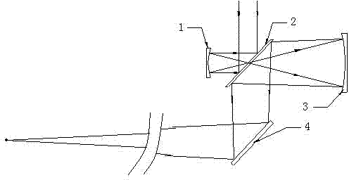
[0013] Such as figure 1 As shown, the coaxial helium-neon laser and carbon dioxide laser are reflected on one side of the small-diameter concave mirror 1 through the double-plane mirror 2, and then reflected by the small-diameter concave mirror 1 and passed through the central hole of the double-plane mirror 2 to the large-diameter concave mirror 3, After the large-diameter concave mirror 3 is reflected to the other side reflected by the double plane mirror 2, the double plane mirror 2 is reflected to the rotating plane mirror 4, and the rotating plane mirror 4 reflects the He-Ne laser and the carbon dioxide laser to the specified position and focuses on one point.

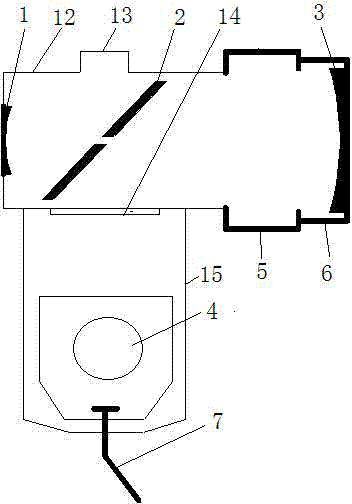
[0014] Such as figure 2 , image 3 As shown, the present invention includes a cylindrical shell 12. The cross section of the cylindrical shell 12 can be circular, also can be polygonal, ...


PUM


Abstract

The invention relates to medical laser treatment instruments, in particular to a laser microsurgery sighting device. The sighting device comprises a cylindrical shell. The sighting device is characterized in that: a small diameter concave mirror is arranged at one end of the cylindrical shell, and the other end of the cylindrical shell is connected with a focusing cylinder through adjusting threads; a big diameter concave mirror is arranged in the focusing cylinder, and the axis of the small diameter concave mirror is superposed with that of the big diameter concave mirror; a double plane mirror which forms an angle of 45 degrees with the axis is arranged in the cylindrical shell; the double plane mirror is provided with a light transmission hole in the axis direction; the wall of the cylindrical shell on one side of the double plane mirror and the small diameter concave mirror is provided with a light inlet arm interface; the wall of the cylindrical shell on one side of the double plane mirror and the big diameter concave mirror is provided with a light outlet; and the cylindrical shell is provided with a rotary plane mirror support, a rotary plane mirror is connected with the support through a handle adjustor, and the included angle between the rotary plane mirror and the light outlet is 70 to 75 degrees. The sighting device is easy to machine and assemble and convenient to operate, has the advantages of good treatment effect and the like, and enlarges the application range of carbon dioxide laser in medical instruments.

Description

technical field [0001] The invention relates to a medical laser therapy appliance, in particular to a medical laser microsurgical aimer which is easy to process, assemble and operate, and is especially suitable for carbon dioxide. Background technique [0002] As we all know, carbon dioxide laser is widely used in clinical practice due to its advantages of high energy, high power, and good therapeutic effect; however, because the light is invisible, visible helium-neon laser is usually used as auxiliary indicator light; At the same time, the aberration formed by the coaxial helium-neon laser and carbon dioxide laser can be widely accepted in body surface cutting surgery; , is the coaxial He-Ne laser and CO2 laser used at the double-lens long focal length; Due to the aberration of this kind of light, the coaxial helium-neon laser and carbon dioxide laser cannot be completely overlapped at the focal point through the double lens, and it is difficult to achieve precise surgery...

Claims


Application Information

Patent Timeline
Patent Type & Authority Patents(China)
IPC IPC(8): A61B18/20
Inventor 李智强王岩
Owner WEIHAI GAOKE MEDICAL EQUIP
Why Eureka
Try Eureka