
Infrared sensor lamp

A technology of infrared induction and infrared sensor, which is applied in the field of infrared induction lamps, can solve problems such as complex circuits and inconvenience, and achieve the effects of high reliability and energy saving

Inactive Publication Date: 2012-08-01
张伟
View PDF2 Cites 2 Cited by
  • Summary
  • Abstract
  • Description
  • Claims
  • Application Information

AI Technical Summary

Problems solved by technology

However, the circuit of this kind of energy-saving lamp is relatively complicated, and it is also inconvenient in actual use.

Method used


Image

  • Infrared sensor lamp

Examples


Embodiment Construction

[0011] In order to make the technical means, creative features, goals and effects achieved by the present invention easy to understand, the present invention will be further described below in conjunction with specific illustrations.

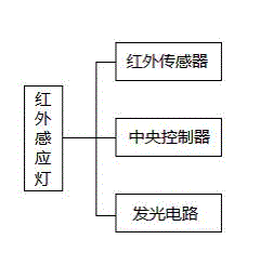
[0012] like figure 1 An infrared induction lamp according to the present invention is shown, which includes a light-emitting circuit. The infrared induction lamp also includes an infrared sensor for sensing infrared heat of the human body. The infrared sensor is connected to the central controller and is controlled by the central controller. For upper control, the central controller is connected with the light emitting circuit, and is used to control the light emitting circuit to be turned on or off. The working principle of the present invention is: when the infrared sensor located outside the induction lamp detects the infrared signal of the human body, it will send a digital signal to the central controller, and the central controller will tu...


PUM


Abstract

The invention discloses an infrared sensor lamp. The infrared sensor lamp comprises a light-emitting circuit and is characterized in that the infrared sensor lamp further comprises an infrared sensor for sensing infrared heat of a human body, the infrared sensor is connected with a central controller and subject to upper control of the central controller, and the central controller is connected with the light-emitting circuit and used for controlling the opening or closing of the light-emitting circuit. The working principle of the infrared sensor lamp disclosed by the invention is as follows: when the infrared sensor positioned outside the sensor lamp detects an infrared signal of the human body, digital signals are sent to the central controller, and after the central controller receives the digital signals, the light-emitting circuit is started; and when the infrared signal of the human body is separated from the sensing range of the infrared sensor, the infrared sensor does not send the digital signals any more, so that the light-emitting circuit is further closed.

Description

technical field [0001] The invention relates to the field of lamp lighting, in particular to an infrared induction lamp. Background technique [0002] The automatic induction lamp has been used more and more in various public places because of its intelligent energy-saving features. The application document with the application number 200920097640 discloses an automatic induction energy-saving lamp, including a detection circuit, a control circuit and a load circuit. The detection circuit, the control circuit and the load circuit are electrically connected to each other in sequence. The detection circuit outputs the detected electrical signal to the control circuit, and the control circuit controls the on-off of the load circuit. The detection circuit is a microwave induction controller, and the control circuit is composed of an integrated circuit. Composed of CD4011BP and the peripheral circuit of the integrated circuit, the load circuit is composed of 12 to 60 LED lamps in...

Claims


Application Information

Patent Timeline
Patent Type & Authority Applications(China)
IPC IPC(8): F21V23/04H05B37/02
Inventor 张伟
Owner 张伟
Learn More