
Data output and input method realized by aid of point codes

An input method and point coding technology, applied in the field of point coding, can solve the problems of difficult discrimination, misinterpretation of optical devices, increased printing difficulty, etc., and achieve the effect of good visual effect.

Active Publication Date: 2012-08-01
SONIX TECH
View PDF8 Cites 17 Cited by
  • Summary
  • Abstract
  • Description
  • Claims
  • Application Information

AI Technical Summary

Problems solved by technology

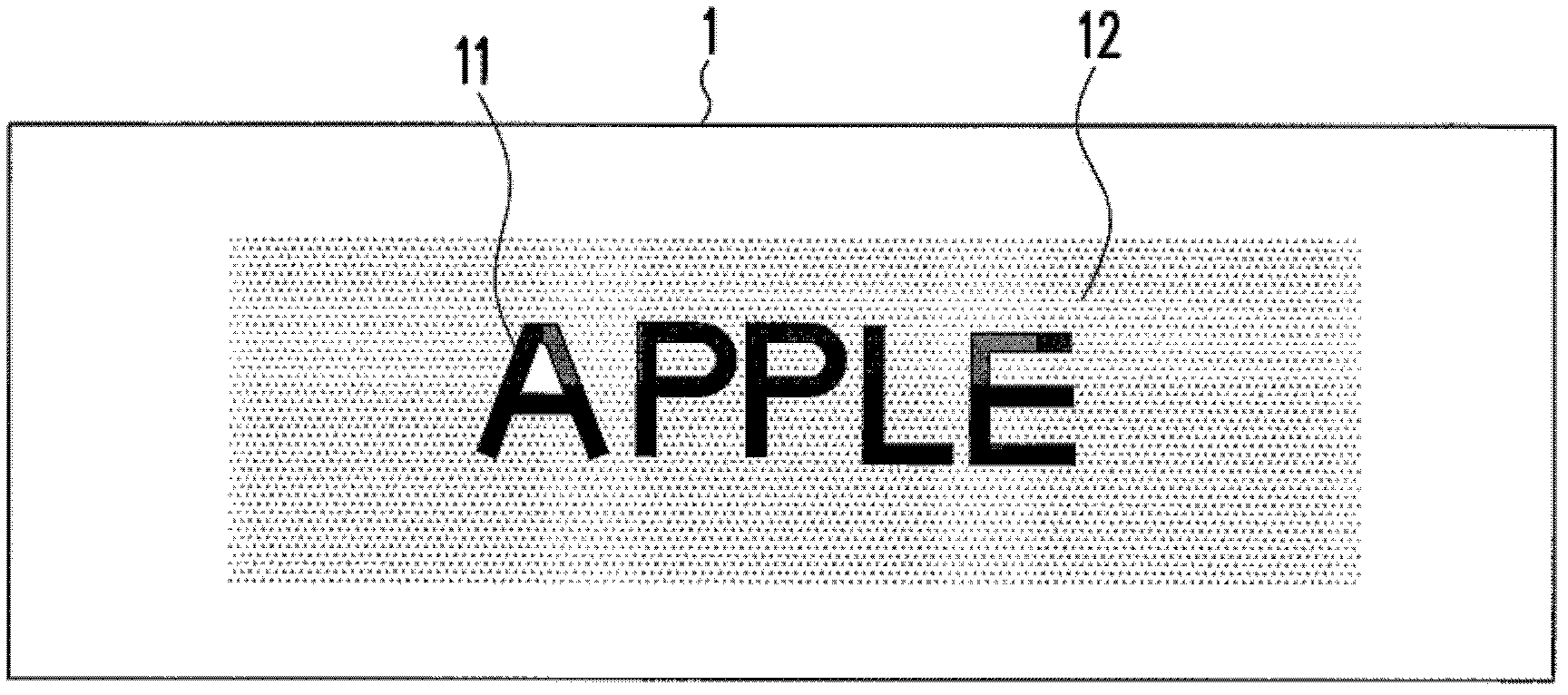
[0005] like figure 1 As shown, the point code 12 usually coexists with the content information 11 on the object surface 1, therefore, when the density of the site is higher, the visual effect is worse, and it is easier for human eyes to perceive the existence of the point code 12 and make the point code 12 Increased chance of confusion with content information 11
On the other hand, when the point code 12 is formed on a limited object surface area, under the premise of providing the same amount of information, too high a point distribution density will cause the distance between two adjacent points to be too small, so when the position When dots are formed on paper by printing, for example, it will cause more obvious visual interference; if you want to reduce this visual interference, you usually need to further reduce the size of the dots, which will increase the resolution requirements of the printing machine and paper, and print It is also easy to miss dots during printing, which relatively increases the difficulty of printing, and it is easy to cause errors in the interpretation of optical devices or difficult to distinguish
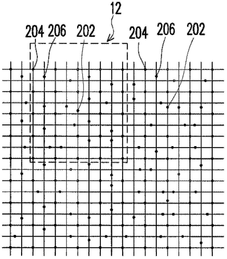
image 3 The known point code 12 design method shown obviously leads to an excessively high site density, and produces the above-mentioned various problems

Method used


Image

  • Data output and input method realized by aid of point codes
  • Data output and input method realized by aid of point codes
  • Data output and input method realized by aid of point codes

Examples


Embodiment Construction

[0063] Figure 4 It is a schematic diagram of a pattern formed by arranging a plurality of dot codes 10 according to an embodiment of the present invention. In order to clearly illustrate the design of the present invention, Figure 5 yes Figure 4 An enlarged schematic diagram of one of the point codes 10 in . Figure 6 It is a flow chart of forming the dot code 10 according to an embodiment of the present invention, and is used to illustrate the steps of forming the dot code 10 . Please also refer to the following Figure 5 and Figure 6 .

[0064] As described in step S610, first divide a plurality of blocks (Block) on the area where a group of point codes 10 are to be formed, for example Figure 5 block 110. The blocks are arranged in a matrix (Matrix), adjacent to each other and not overlapping each other. In step S620, each block is further divided into a plurality of bit zones (BitZones). by Figure 5 For example, each block can further be divided into 9 bit a...


PUM


Abstract

Disclosed are point codes read by the aid of image recognition and a data output / input method realized by the aid of the point codes. The data output / input method includes that at least one point code corresponding to pointer data is formed on the surface of an object, each point code consists of a plurality of blocks, and each block is provided with a locus. Each block is partitioned into a plurality of locus regions which are arrayed, and parts of the locus regions which are arrayed into a cross shape form a mark region. The loci forming contents of the data of the point codes are arranged in the locus regions out of the mark regions of the blocks. The loci forming mark contents of the point codes are arranged in the locus regions in the mark regions of the blocks, and the surface of the object is read optically so as to obtain the pointer data corresponding to the point codes.

Description

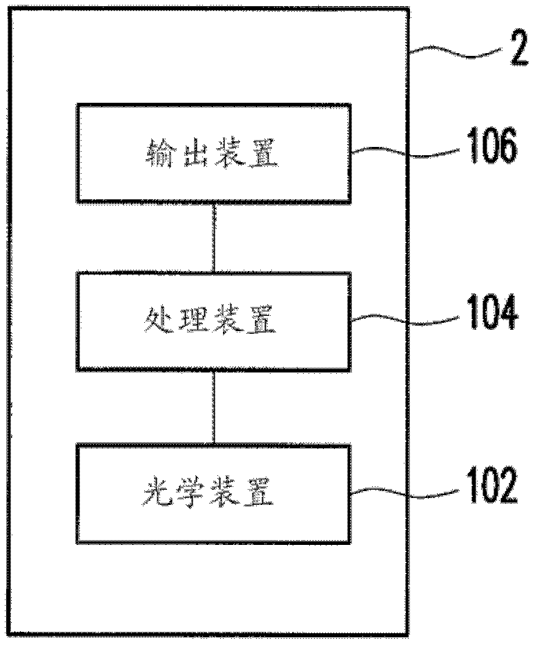
technical field [0001] The present invention relates to a dot code that can be read by pattern / image recognition. The dot code is formed on the surface of an object and corresponds to a pointer data. Background technique [0002] figure 1 It is a schematic diagram showing a dot code (Dot Code) 12 formed on a surface 1 of an object. Such as figure 1 As shown, the dot code 12 is composed of many bit dots. Since the bit dots are quite small, they are easily ignored visually, or interpreted as the background color by human eyes. Point code 12 and content information (Information Material) 11 (such as figure 1 The character pattern "APPLE") is jointly formed on the surface 1 of an object such as paper by means of printing or the like. The point code 12 is mapped to a pointer data and does not affect the reception of the content information 11 by human eyes. [0003] figure 2 To show a schematic diagram of an electronic system 2 , the electronic system 2 has an optical devi...

Claims


Application Information

Patent Timeline
IPC IPC(8): G06K9/46
Inventor 黄资峰
Owner SONIX TECH
Learn More